
Temporary soil sheathing apparatus

A technology of supporting device and soil layer, applied in construction, excavation, infrastructure engineering, etc., can solve the problems of reducing working space, increasing construction cost, reducing work efficiency, etc., to increase working space, reduce material use, and improve work efficiency. The effect of efficiency

Active Publication Date: 2008-11-19
SUPPORTEC CO LTD
View PDF5 Cites 41 Cited by
  • Summary
  • Abstract
  • Description
  • Claims
  • Application Information

AI Technical Summary

Problems solved by technology

This becomes a factor that increases the construction cost and complicates the structure
Also, the workspace is reduced, reducing productivity

Method used


Image

  • Temporary soil sheathing apparatus
  • Temporary soil sheathing apparatus
  • Temporary soil sheathing apparatus

Examples


Embodiment 3

[0082][79] The temporary soil layer support device according to the third embodiment of the present invention further includes a corner connection structure, which is arranged in a row at each corner when performing excavation work for constructing an underground structure, and in a truss structure Integral, suitable for uniform transmission of horizontal loads, so that sufficient capacity to withstand bending loads is obtained using coupling beams.

[0083] [80] Referring to FIGS. 9 to 13, the temporary soil layer support device according to the third embodiment of the present invention includes: coupling beams 1100, which are obliquely arranged in rows at each corners, and both ends are supported on the supporting wall 1010; and at least one connection plate 1200 interconnecting the upper or lower surfaces of adjacent coupling beams 1100 using coupling members.

[0084] [81] More specifically, the connection plate 1200 has a rectangular shape, and has at least one rigid memb...


PUM


Abstract

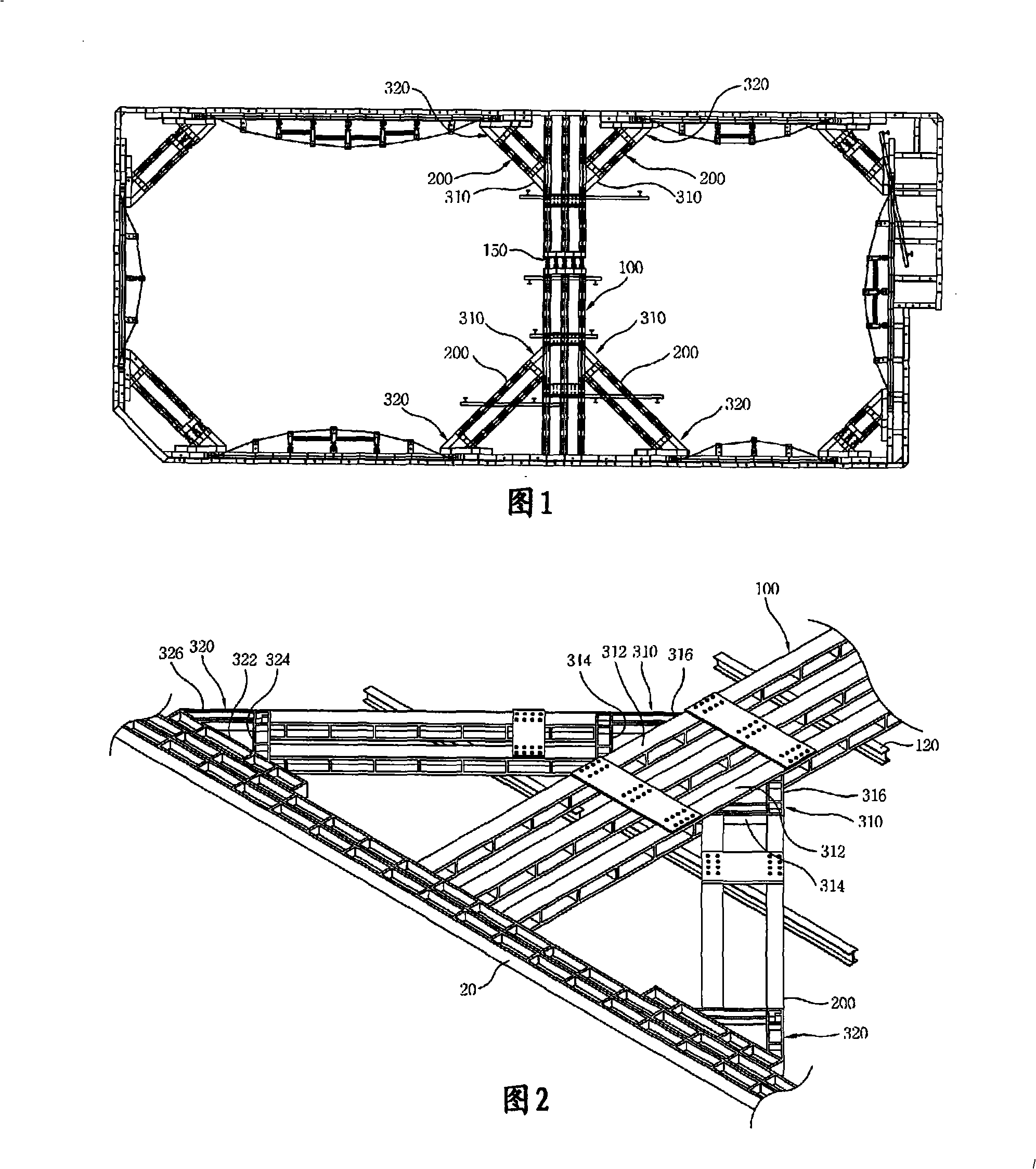
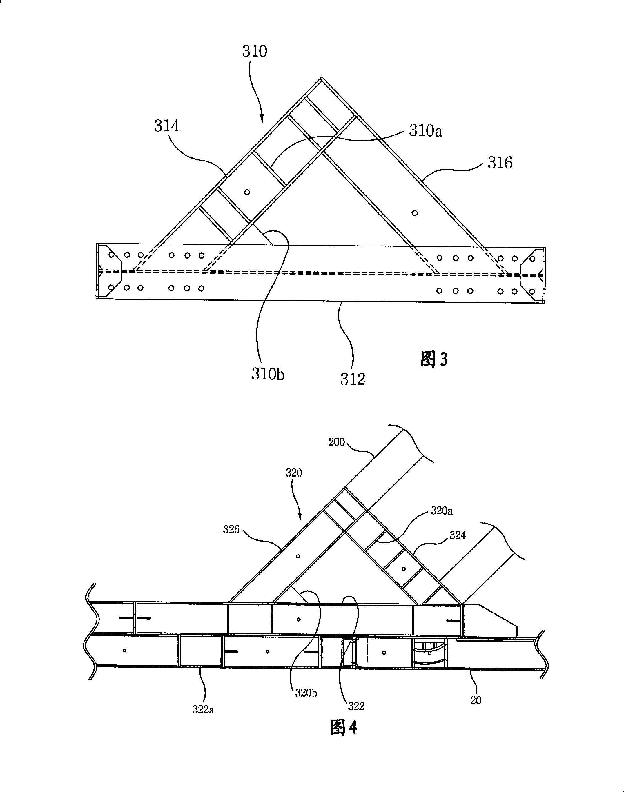
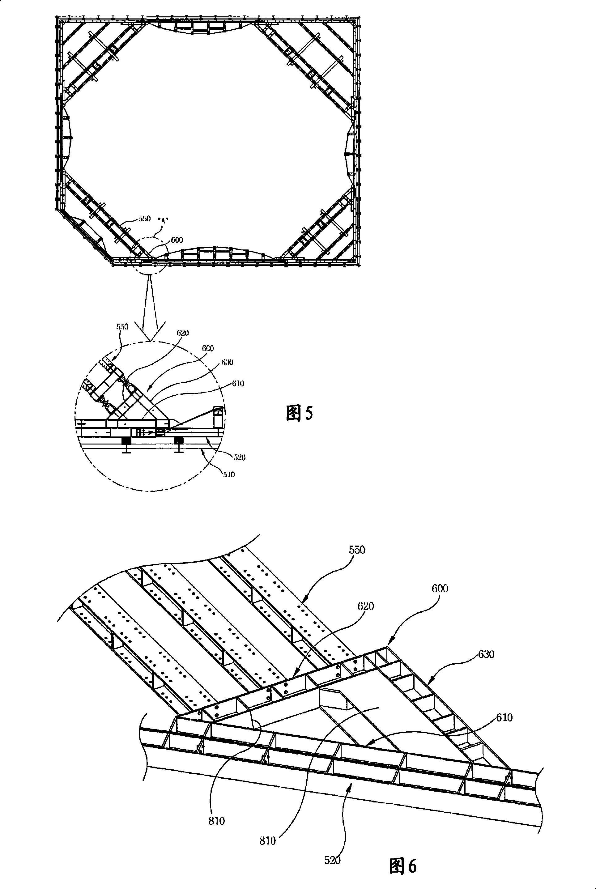
A temporary soil sheathing apparatus supports a set of intermediate bracing beams in a triangular supporting structure during pit excavation work for constructing an underground structure, so that it can satisfactorily support soil pressure. Thus, it is possible to prevent space from being reduced by a complicated supporting structure, reduce construction costs through reduced use of materials, and increase work space to improve productivity. The temporary soil sheathing apparatus simplifies a corner connecting structure, and reinforces ability to withstand the soil pressure transmitted from the bracing beams and wales. Thereby, it is possible to prevent space from being reduced by a complicated supporting structure, reduce construction costs through reduced use of materials, and increase work space to thus improve productivity.

Description

technical field [0001] [01] Generally speaking, the present invention relates to a temporary soil layer support device, and more particularly, to a temporary soil layer support device capable of Improve soil pressure bearing capacity. Background technique [0002] [02] It is known to those skilled in the art that, in subway construction or excavation work to form the foundation of a building, holes are drilled to a predetermined depth in a designated area and then vertical piles are inserted into the holes. After the pilings have been inserted, the ground will be partially excavated and the wide I-beams and lining will be installed. After the liner is installed, the rest of the ground will be excavated, with repeated hitch beam installations during the excavation process. Therefore, in order to design such a temporary structure, it is necessary to repeatedly calculate the earth pressure and load acting on each tie beam for each excavation step, and install the tie beams in...

Claims


Application Information

Patent Timeline
Patent Type & Authority Applications(China)
IPC IPC(8): E02D17/04
CPCE02D17/04
Inventor 白承德
Owner SUPPORTEC CO LTD
Learn More