Probe apparatus and detection apparatus

A technology for inspection devices and probes, which is applied in the directions of measuring devices, electronic circuit testing, instruments, etc., can solve the problems of deflection of thin-film probes 41, fewer contacts 43, and non-existence.

Inactive Publication Date: 2008-10-29
NIHON MICRONICS
View PDF2 Cites 13 Cited by
  • Summary
  • Abstract
  • Description
  • Claims
  • Application Information

AI Technical Summary

Problems solved by technology

[0022] However, in this case, if the sheet-shaped elastic film 42 is used to pressurize the contacts 43 arranged in a plurality of staggered rows, as in Figure 11 As shown, there is the following problem: in the central part of the region where a plurality of contacts 43 are arranged, each contact 43 receives a pressing force, and in the peripheral part, the number of contacts 43 becomes few or does not exist, and due to the uniformly applied pushing force Thin film probe 41 bends due to pressure, and each contact 43A in the center floats up, causing problems such as poor contact

Method used


Image

  • Probe apparatus and detection apparatus
  • Probe apparatus and detection apparatus
  • Probe apparatus and detection apparatus

Examples


Embodiment Construction

[0047] Next, a probe device and an inspection device according to an embodiment of the present invention will be described with reference to the drawings. The inspection device according to the present embodiment is substantially the same as the above-mentioned conventional inspection device, and therefore, the probe device will be mainly described here. In addition, it can be applied to all devices that can use the probe device of this embodiment as an inspection device.

[0048] The probe apparatus 1 of this embodiment is an apparatus used for the inspection apparatus of a liquid crystal panel. The liquid crystal panel has a rectangular shape, and a plurality of electrodes (not shown) are formed at predetermined pitches on edges corresponding to two adjacent sides of the rectangle.

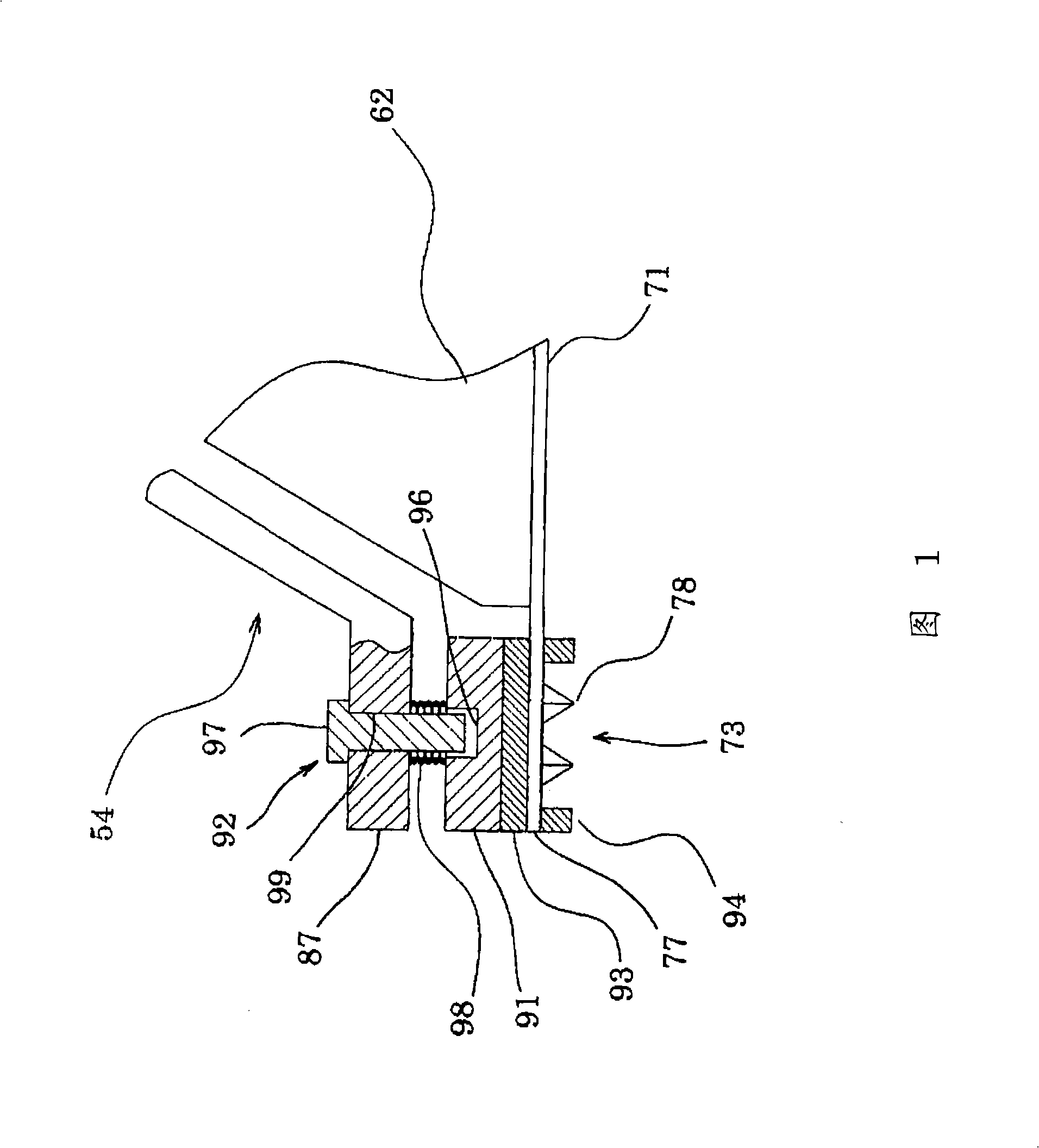
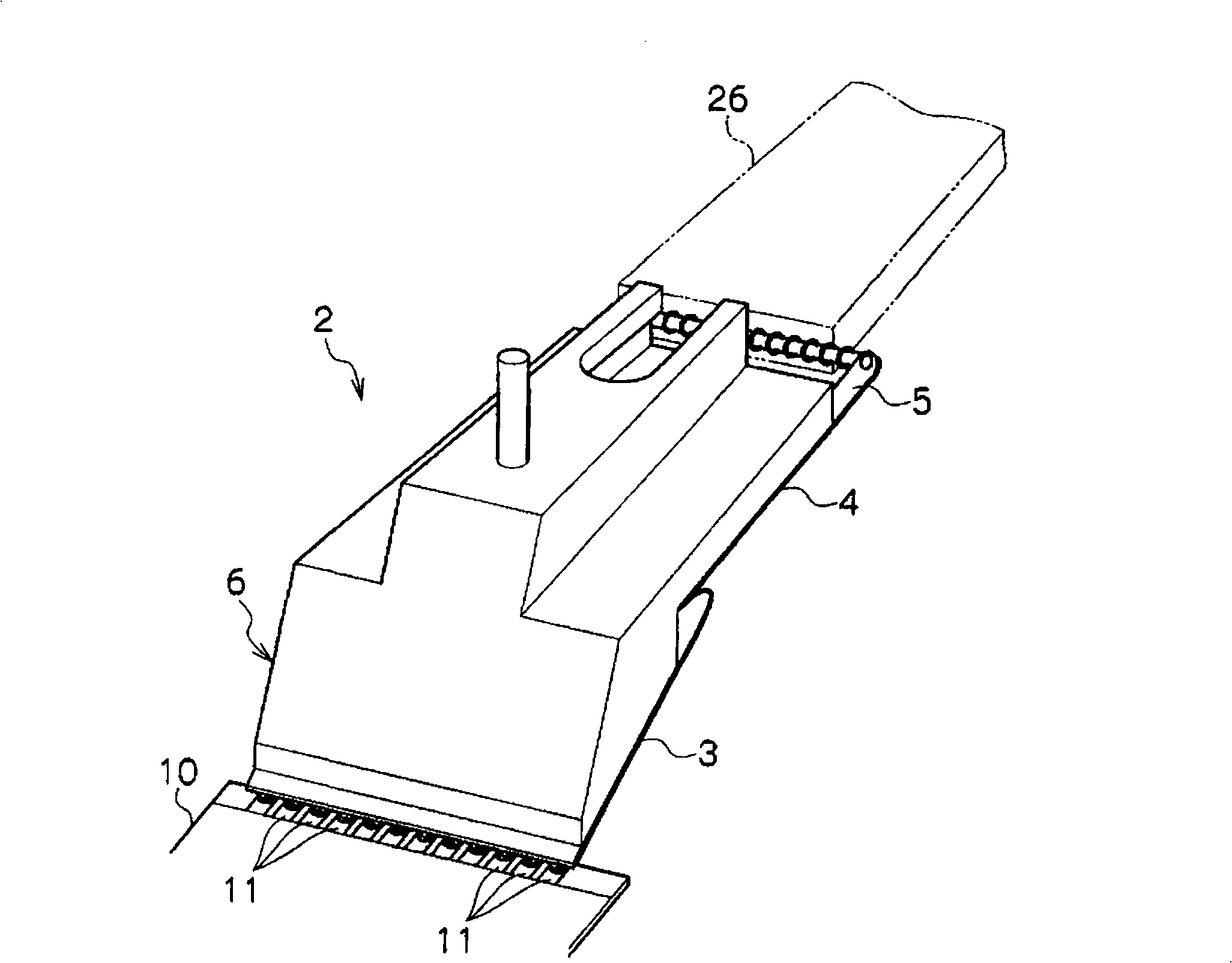
[0049] As shown in FIGS. 12 to 14 , the probe device 51 is configured to include a probe base 52 , a probe block 53 , and a pressurizing mechanism 54 .

[0050] The probe base 52 is a member f...


PUM


Abstract

The invention provides a probe device and a detection device, to ensure each contact terminal of a membrane probe in contact with the electrode of the detected body accurately. The probe device includes: a probe base fixed at the body frame side, a probe block which bears the membrane probe and ensures the membrane probe in electrical contact with the electrode of the detected body, and a pressurizing mechanism which pressurizes the membrane probe by uniform pressure under the state that each contact terminal of the membrane probe is in contact with the electrode of the detected body. The pressurizing mechanism includes a top pressurizing part, which contacts with the membrane probe directly, and pressurizes the membrane probe under the state that each contact terminal of the membrane probe is in contact with the electrode of the detected body; the top pressurizing part is composed of a pressurizing plate for pressurizing the membrane probe, an elastic body which becomes uniform by using the pressure exerted by the pressurizing plate, and a bearing membrane which is arranged at one side of the contact terminal of the membrane probe and combines with the elastic body mutually to ensure that the pressure exerted on each contact terminal becomes uniform.

Description

technical field [0001] The present invention relates to a probe device and an inspection device for inspecting flat-shaped objects to be inspected such as liquid crystal panels and integrated circuits. Background technique [0002] Usually, a flat-plate-shaped object to be inspected, such as a liquid crystal panel, is inspected using a probe device such as a probe card. As one of such probe devices, it is known to use a probe sheet in which a plurality of wirings extending parallel to each other are formed on one side of an electrically insulating film, and a part of each wiring is used as a probe element. use. This example is disclosed in Patent Document 1. Next, the invention of this patent document 1 will be outlined. [0003] Such as figure 2 As shown, the structure of the probe device 1 includes a probe block 2 . In the illustrated example, the probe block 2 is composed of a probe sheet 3, a sheet-shaped first connection sheet 4 connected to the probe sheet 3, a se...

Claims


Application Information

Patent Timeline
Patent Type & Authority Applications(China)
IPC IPC(8): G01R1/067G01R31/00G01R31/28
Inventor 安田贵生久我智昭
Owner NIHON MICRONICS
Why Eureka
Try Eureka