
Phase correcting method and device for display signal

A display signal and phase correction technology, applied in the field of image processing, can solve the problems of cumbersome operation process and waste of time, and achieve the effect of avoiding tediousness

Inactive Publication Date: 2010-07-21
GUIYANG HISENSE ELECTRONICS
View PDF3 Cites 0 Cited by
  • Summary
  • Abstract
  • Description
  • Claims
  • Application Information

AI Technical Summary

Problems solved by technology

Obviously, it is a waste of time to achieve a normal display through manual, experimental and repeated adjustments by the user, and the operation process is also quite cumbersome

Method used


Image

  • Phase correcting method and device for display signal
  • Phase correcting method and device for display signal
  • Phase correcting method and device for display signal

Examples


Embodiment Construction

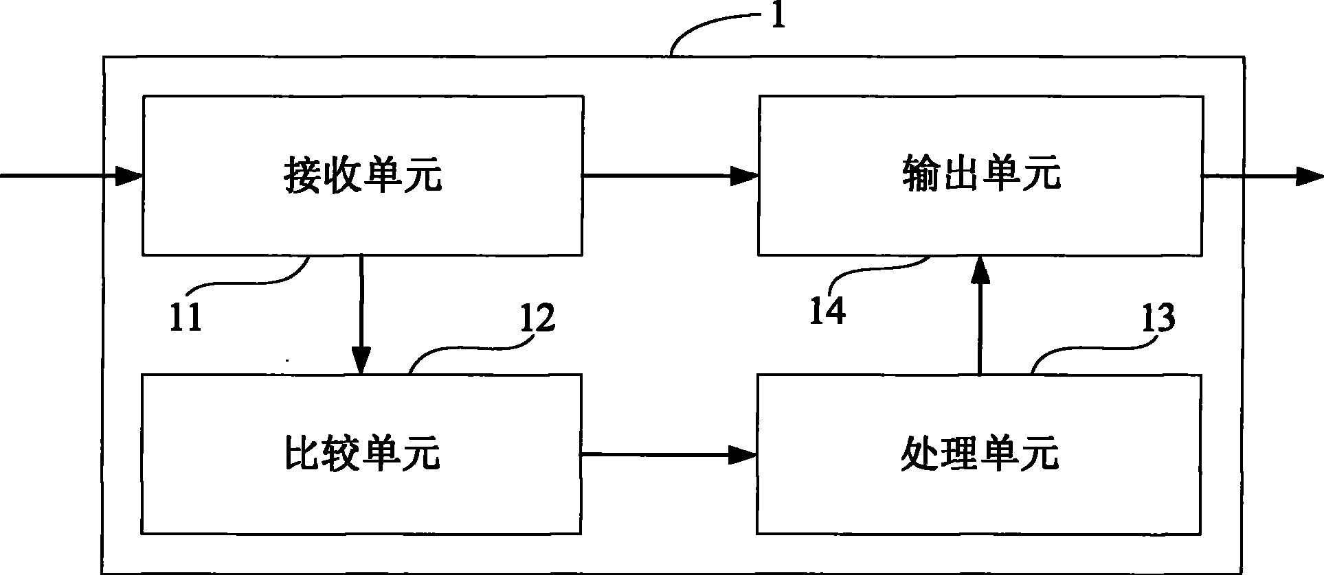
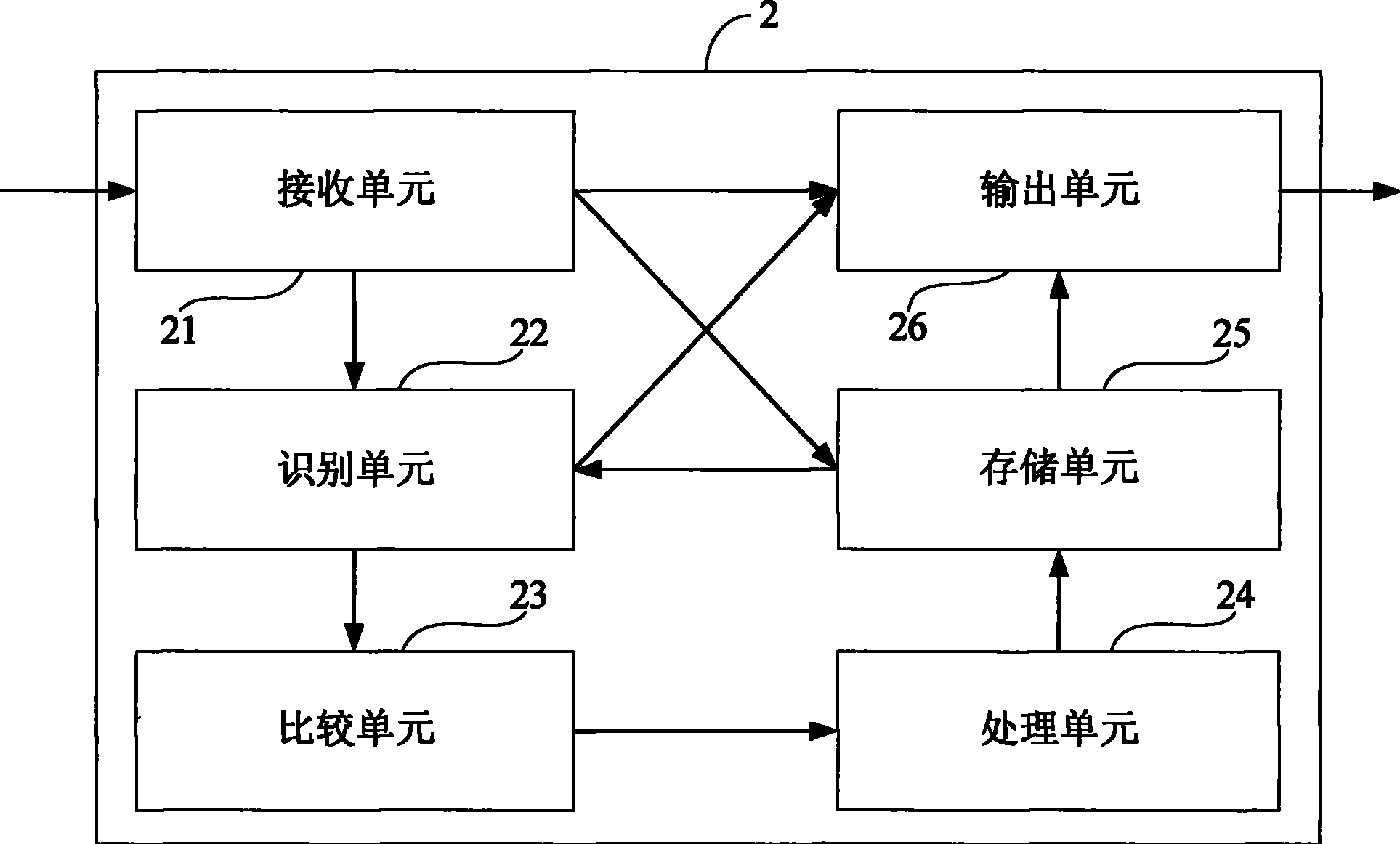
[0034] refer to figure 1 , illustrates the functional structure of an embodiment of a display signal phase correction device of the present invention. As shown in the figure, the display signal phase correction device 1 includes:

[0035] The receiving unit 11 is used to receive the parameters of the display signal to be corrected; wherein, the parameter of the display signal to be corrected can be a VGA signal or a video signal in other appropriate formats, and the display signal comes from a signal source, such as a DVD player, a PC, etc. ; In addition, the display signal parameters to be corrected include at least a synchronization width parameter, a synchronization trailing edge width parameter, and a synchronization polarity parameter, and may also include an effective width parameter, a total width parameter, and a synchronization front edge parameter, etc., and these parameters may be the described The related parameters of the line signal or the related parameters of ...


PUM


Abstract

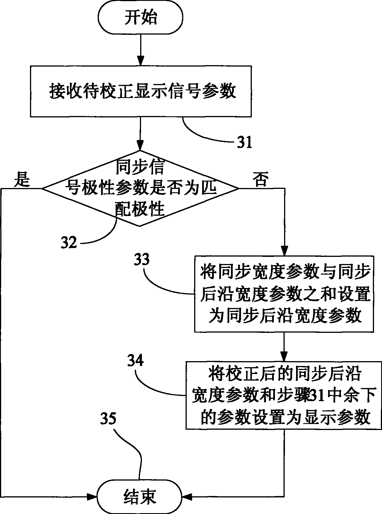
The invention discloses a method for the phase correction of a display signal. The method comprises the following steps that: (a) a to-be-corrected display signal parameter is received; (b) whether the synchronous polarity parameter of the to-be-corrected signal is matching polarity is judged; if the judgment is yes, the correction process is stopped; (c) when the synchronous polarity parameter is not matching polarity, the sum of the synchronous width parameter of the to-be-corrected display signal and a synchronous after edge width parameter is set as a synchronous after edge width parameter; (d) the corrected synchronous after edge width parameter is taken as a correction parameter and is set as a display parameter. The method can correct the offsetting or deletion phenomena of image display position caused by certain difference between the signal generated by a signal source and a standard signal, and can avoid the trouble of a user caused by manual adjustment at the same time. Meanwhile, the invention also discloses a device for the phase correction of a display signal.

Description

technical field [0001] The invention belongs to the technical field of image processing, and in particular relates to a phase correction method and device in the field of image processing. Background technique [0002] In daily life, work or other occasions, we sometimes find that the position of the image displayed by the display device is not in the center of the display screen of the display device, but has a certain distance offset; The image displayed on the monitor is missing. This is because the signal sources of the display signals received by the display device are various, and these signal sources may come from many different manufacturers. Because each manufacturer is different, the signal formats of the signal sources produced by them are more or less There is a gap between the standard signal and the standard signal specified by the standard organization. Therefore, in this case, when the standard display device receives the display signal that has a certain ga...

Claims


Application Information

Patent Timeline
Patent Type & Authority Patents(China)
IPC IPC(8): G09G5/00H04N5/00G09G5/38H04N5/44H04N5/445
Inventor 周全
Owner GUIYANG HISENSE ELECTRONICS
Learn More