
Levitating force pressurized pump and tide generation station adopting same

A pressurized pump and power station technology, applied in the field of buoyant pressurized pumps and wave power stations, can solve problems such as high cost, nuclear radiation leaks, pollution, etc., and achieve the effect of low construction and operation costs

Active Publication Date: 2008-10-22
SUZHOU FUERDA TECH CO LTD
View PDF0 Cites 18 Cited by
  • Summary
  • Abstract
  • Description
  • Claims
  • Application Information

AI Technical Summary

Problems solved by technology

There are certain problems in these power stations. The construction of dams to store water and power stations will bring about a large number of immigration problems. It is very difficult for those people who have lived there for generations to leave their homes. The dams have huge potential safety problems. Once Earthquakes, wars, and dam safety may endanger the personal safety and property safety of large areas of the population, and the water storage capacity of reservoirs is greatly affected by seasons and climates. How much impact dams store water change on the natural environment on the environment and climate has always been an issue. Scientists are arguing that the energy consumption of thermal power generation is huge, and the combustion is very polluting to the environment, which is also one of the main factors for the warming of the earth's temperature; the safety of nuclear power plants also makes people worry, and problems such as nuclear radiation and nuclear leakage have always been troubled At present, although the development of solar and wind power generation is vigorously advocated, it has the disadvantages of low power generation, high cost, and high geographical location requirements; some people have thought of tidal power generation for a long time, but the location of the tidal power station is very high, and it must be a bay. Moreover, the difference between tide and evening is large, and there are also disadvantages such as high station construction and operating costs.

Method used


Image

  • Levitating force pressurized pump and tide generation station adopting same
  • Levitating force pressurized pump and tide generation station adopting same

Examples


Embodiment Construction

[0021] The preferred embodiment of the present invention will be described in detail below in conjunction with accompanying drawing:

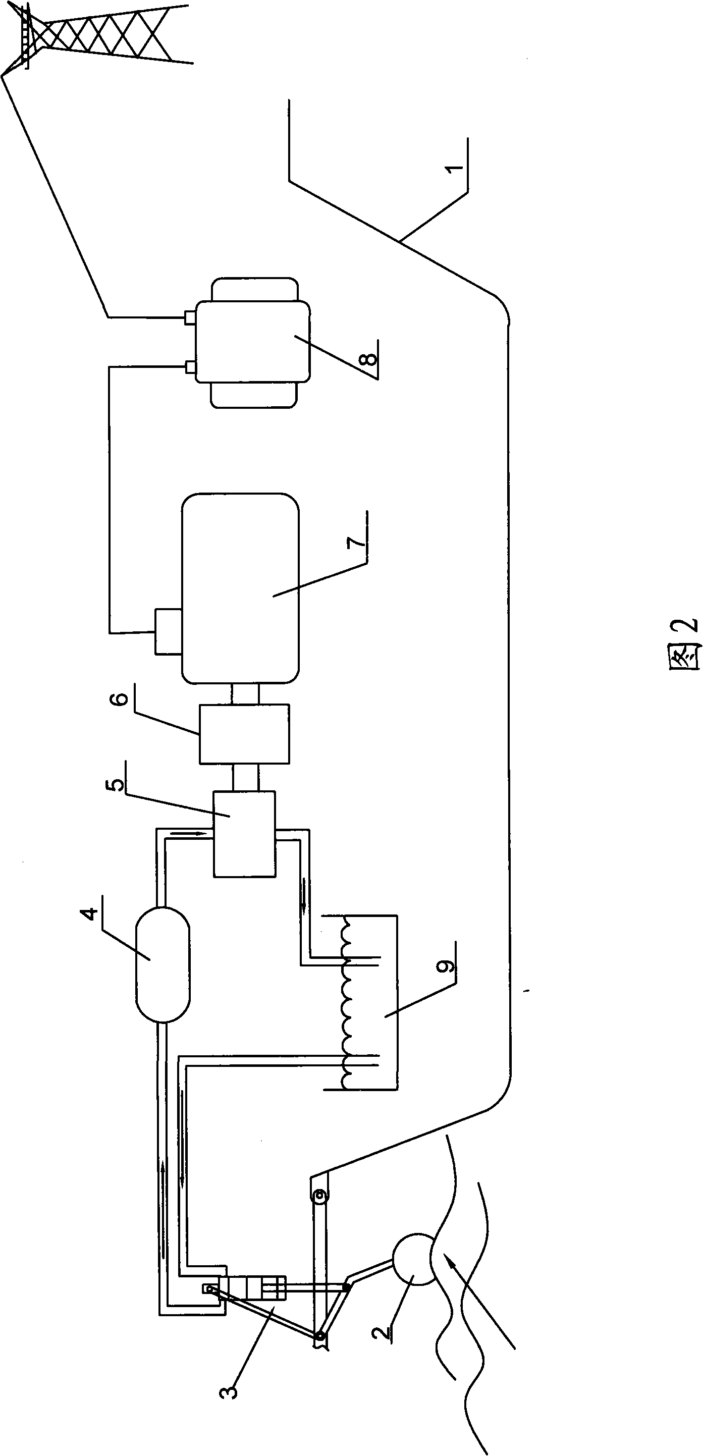
[0022] The wave power station shown in Figure 2 includes a carrier 1 floating on the water, several buoyancy booster pumps 3 arranged around the carrier 1, accumulators 4 respectively arranged on the carrier 1, a driving device 5, and a generator 7. The functional parts are introduced as follows:

[0023] The carrier 1 can be a ship, which can be moved as needed, so that it can be fixed and anchored at a favorable position to collect more energy.

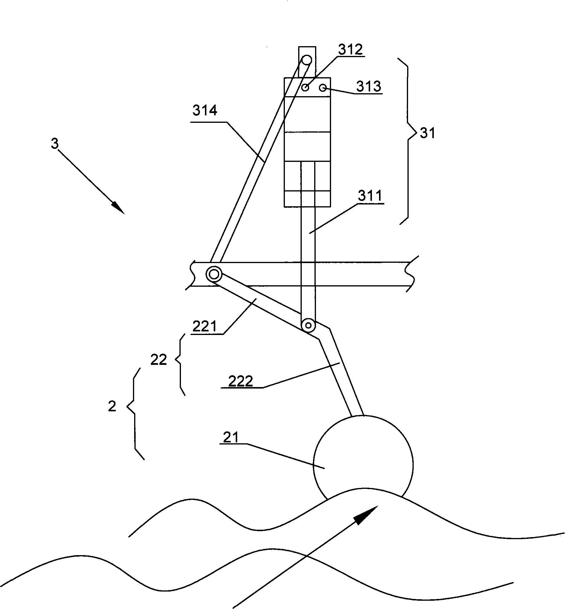
[0024] In the present invention, the buoyancy booster pump 3 is arranged on the periphery of the carrier 1, such as figure 1 As shown, each buoyancy booster pump 3 includes a pump body 31 and a floating body 2. The pump body 31 generally includes a cylinder body and a telescopic piston rod 311 arranged in the cylinder body. The piston rod 311 is connected to the floating body 2. The pump body 31 al...


PUM


Abstract

The invention relates to a method using heaving and dipping of a floating body by wave pushing to ensure energy to be transferred to a driving device in hydraulic energy way through a carrier which is provided with a plurality of buoyancy pressure pumps. The driving device converts the hydraulic energy into mechanical energy to drive a generator to generate electricity. The method has the advantages of non-pollution, low construction and running cost, safety and reliability, large electric quantity, non-occupied land and others. The method makes up for all shortcomings in the prior power plants such as: security problems of water-power plants and nuclear power plants, pollution problems of thermal power generation, high cost and small electric quantity of wind and solar power plants. The method can better meet the human demands for electricity and also can improve life level and production level.

Description

technical field [0001] The invention relates to a pump, in particular to a buoyancy boosting pump for converting buoyancy of water into pressure and a wave power station using the pump. Background technique [0002] The world's energy is becoming increasingly tense, and energy consumption is increasing. In particular, the demand for electricity is more prominent. The existing power generation technologies in the world mainly include damming and water storage (hydropower stations), thermal power generation, nuclear reactor power generation, and a small amount of wind power generation. solar energy generation. There are certain problems in these power stations. The construction of dams to store water and power stations will bring about a large number of immigration problems. It is very difficult for those people who have lived there for generations to leave their homes. The dams have huge potential safety problems. Once Earthquakes, wars, and dam safety may endanger the perso...

Claims


Application Information

Patent Timeline
IPC IPC(8): F04B9/10F04B53/14F03B13/22F03B13/12
CPCY02E10/38Y02E10/30
Inventor 朱力克
Owner SUZHOU FUERDA TECH CO LTD
Learn More