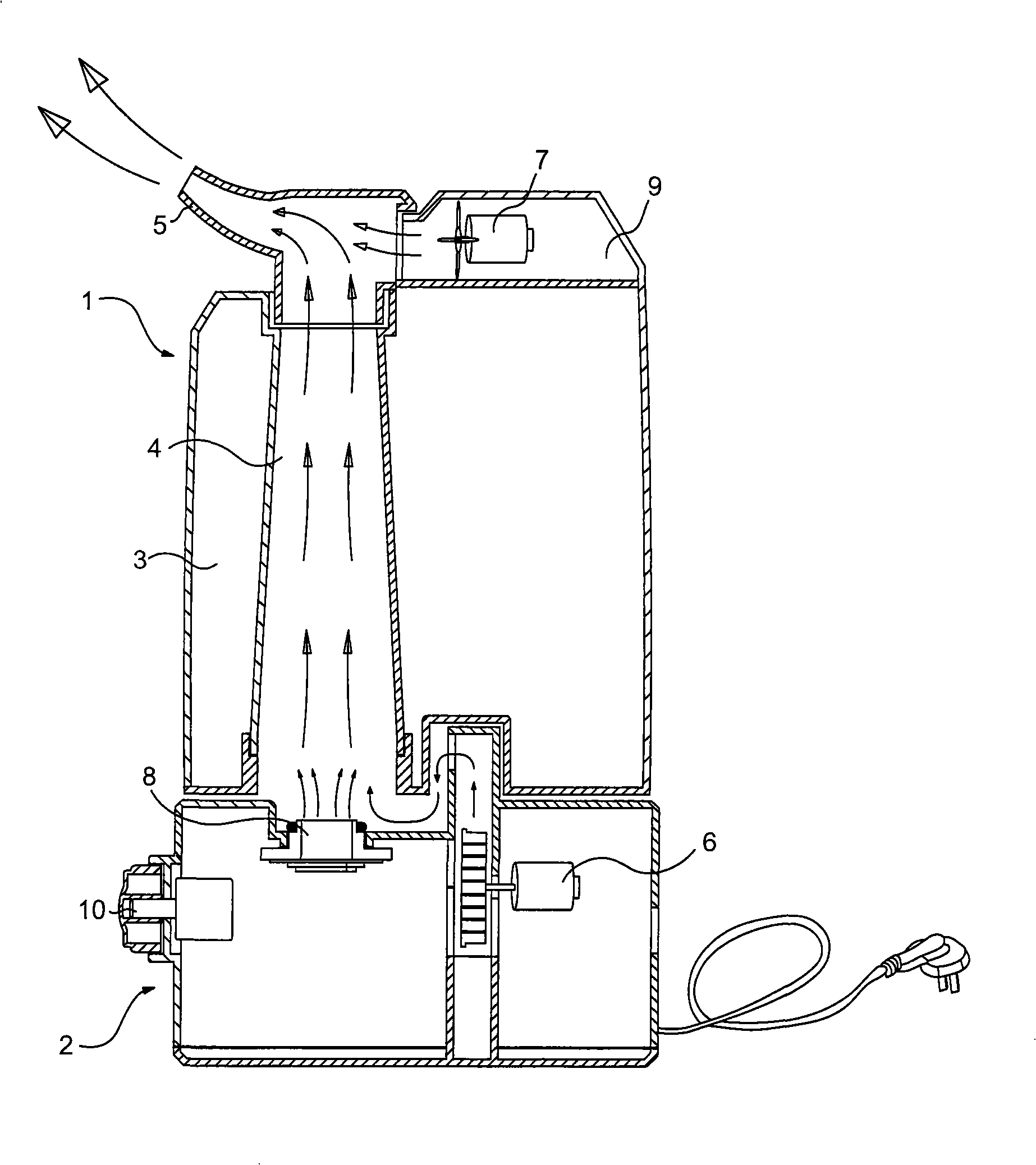
Air humidifier
An air humidifier and airflow technology, applied in the direction of air humidification system, heating method, lighting and heating equipment, etc., can solve the problems of no further diffusion, weak nozzle strength, pollution, etc., and achieve the effect of avoiding condensation into droplets
Inactive Publication Date: 2008-10-15
卞庄
View PDF1 Cites 18 Cited by
- Summary
- Abstract
- Description
- Claims
- Application Information
AI Technical Summary
Problems solved by technology
Although this humidifier can increase the water storage capacity of the water tank and make the structure of the water tank beautiful, it still suffers from the following problems: since the nozzle is installed above the water tank, and the transducer sheet is located at the bottom of the water tank, so The length of the mist guide is long, relying on the power of a single fan located in the base to blow the water mist out of the nozzle is too small, so that after the water mist escapes outside the humidifier, it cannot spread further, that is to say, the water mist sprayed from the nozzle The air can only be humidified in a limited area, and if the water mist humidifies the air in a limited area, a large amount of water mist will remain in the air in this area, which will inevitably increase the humidity of the air in this area. Rapid saturation, so that the water mist sprayed from the nozzle can easily condense into droplets and fall down in this area due to the inability to diffuse well, causing pollution
Method used
View moreImage
Smart ImageViewing Examples
Examples
Embodiment Construction
Login to View More PUM
 Abstract
The invention relates to an air humidifier, which comprises an upper box and a lower box, wherein, the inner cavity of the upper box is divided into a water storage chamber and a mist guide chamber; a nozzle is arranged on the upper part of the upper box, and the nozzle is communicated with the mist guide chamber through the airflow; the inside of the lower box is provided with a transduction plate capable of atomizing the water flowing out of the water storage chamber, and also provided with a main fan capable of taking the atomized water to the nozzle from the mist guide chamber and blowing off the atomized water; the humidifier is also provided with an auxiliary fan nearby the nozzle, and the auxiliary fan is capable of blowing the water mist taken by the main fan to the nozzle at a farther distance. The air humidifier has the advantages that: with the auxiliary fan nearby the nozzle, the water mist taken by the main fan to the nozzle can be blown far away so as to quickly humidify larger area outside and avoid condensing to droplets in a small area.
Description
air humidifier technical field The invention relates to an air humidifier. Background technique At present, the most widely used air humidifier is the ultrasonic air humidifier. Its working principle is to use a transducer (also called an oscillating plate) to convert electrical energy into mechanical energy and generate high-frequency oscillations of about 1.7 million times per second. The water is atomized into ultra-fine particles of 1-5 microns, and then the water is blown into the outside air by a fan to increase the humidity of the environment. The Chinese utility model patent No. 200320131579.2 discloses a double water tank humidifier, which includes a base (equivalent to the lower tank), a water tank, and a nozzle. The transducing sheet, fan and control circuit to be processed, the transducing sheet is arranged in the middle of the base, and the base is symmetrically provided with two water tanks on both sides of the transducing sheet, above the air outlet of the...
Claims
Login to View More Application Information
Patent Timeline
 Patent Type & Authority Applications(China)
IPC IPC(8): F24F6/14
Inventor 卞庄
Owner 卞庄
Features
- R&D
- Intellectual Property
- Life Sciences
- Materials
- Tech Scout
- Unparalleled Data Quality
- Higher Quality Content
- 60% Fewer Hallucinations
Learn More Browse by: Latest US Patents, China's latest patents, Technical Efficacy Thesaurus, Application Domain, Technology Topic, Popular Technical Reports.
© 2025 PatSnap. All rights reserved.Legal|Privacy policy|Modern Slavery Act Transparency Statement|Sitemap|About US| Contact US: help@patsnap.com

