Magnetic Rotary Device
A rotating device and magnetic suction technology, which is applied in transmission control, toys, entertainment, etc., can solve problems such as sealing and achieve good results
- Summary
- Abstract
- Description
- Claims
- Application Information
AI Technical Summary
Problems solved by technology
Method used
Image

Examples
Embodiment 1
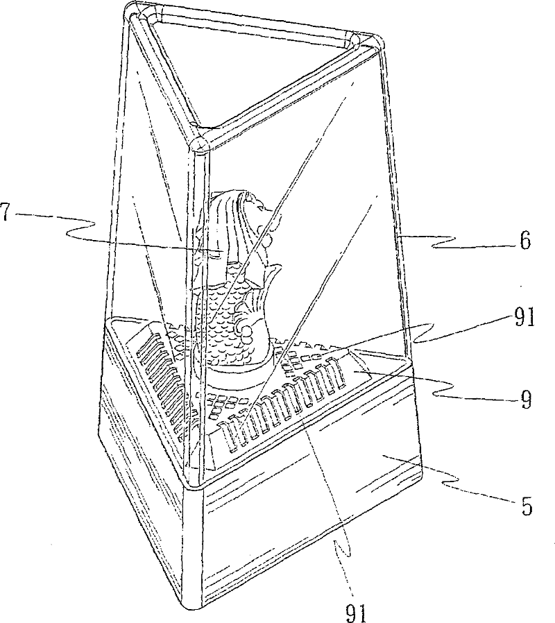
[0030] Such as Figure 1 to Figure 5 As shown, in order to disclose the ornamental cover design that the present invention utilizes the configuration of magnetic suction type rotating device to form, at first explain its constitution to the magnetic suction type rotating device of the present invention,
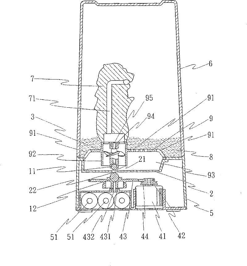
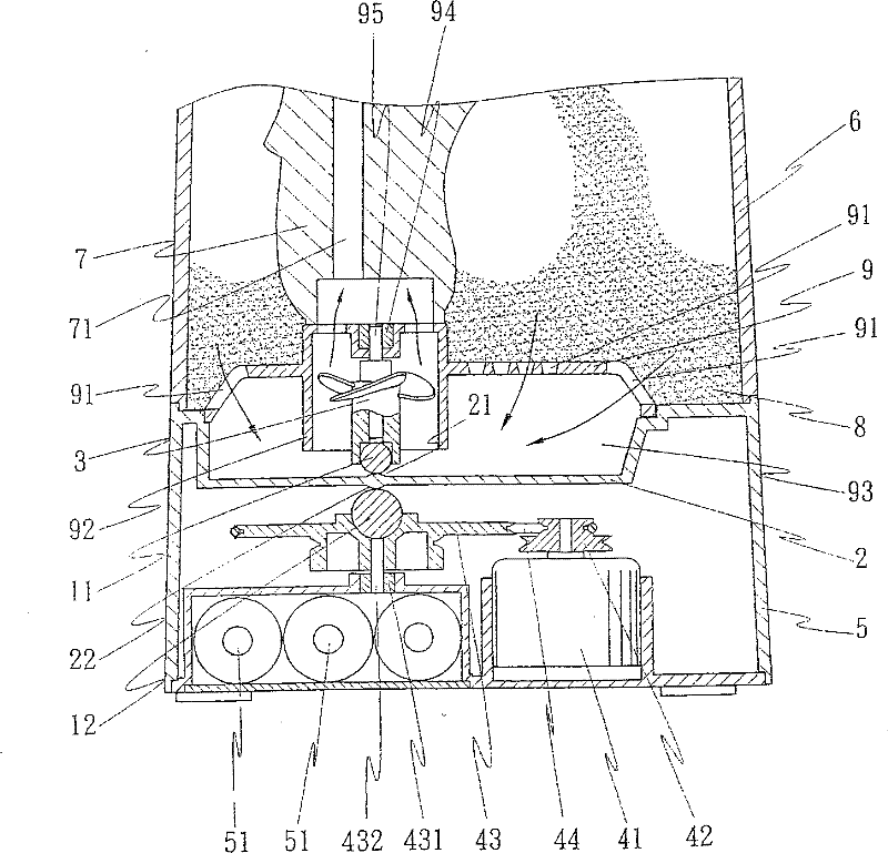
[0031] Such as Figure 4 As shown, the magnetic suction rotating device includes one or more sets of magnetic blocks 11 and 12, a non-magnetic partition 2, a rotating object 3 and a power source 4, and the rotating object 3 can be designed as a blade as required. The base or a member in the shape of a turntable base, wherein:
[0032] One or more sets of magnetic blocks 11 and 12 are arranged on the upper and lower sides of the partition 2 respectively. The upper magnetic block 11 is equivalent to a passive component, while the lower magnetic block 12 is equivalent to an active component. The magnetic block 12 on the side can be controlled and driven by a power source 4, an...
Embodiment 2
[0044] Such as Figure 6 to Figure 9 As shown in the figure, the rotating object 3a is implemented in the form of a turntable base, so that the rotating disk-shaped rotating object 3a can be rotated and driven in space, so that the fluid of the fluid object 8 is subjected to centrifugal force to produce the effect of vortex upward diffusion and propulsion. In the same way, the fluid 8 passes through the central hole 91a of the tray 9a and falls concentratedly into the lower chamber 93a (the surface of the non-magnetic separator 2), and then utilizes the vortex diffusion of the rotating object 3a, so that the fluid 8 can pass through the tray 9a The peripheral perforated hole 91a is sprayed out along the flow, so it can drive the liquid material 8 to form multi-directional churning, so as to create visual effects of different jet scenes.
[0045] The distribution form of the perforated holes 91 or 91a of the tray 9 or 9a can be determined arbitrarily, and can be changed arbitra...
Embodiment 3
[0051] Such as Figure 10 As shown, the power source 4 can be directly driven by the motor 41 to rotate the magnetic block 12, and it is shown that the decorative object 7 can open two spray channels 71 at the same time. Similarly, it can be known that the decorative object 7 can open more spray channels 71 . Above-mentioned rotating object 3 or 3a, no matter it is implemented as a blade seat or a member of a turntable seat form, a bearing 94 can be preset between rotating object 3 or 3a and pallet 9 or 9a, and a shaft The core 95 runs through the rotating object 3 or 3a and is connected to the bearing 94, and the bearing 94 is still sealed and isolated from the ornamental cover 6, so the rotating object 3 or 3a can be guaranteed to rotate smoothly without any leakage. Similarly, the driven wheel 43 of the aforementioned power source 4 may also be configured with a bearing 431 and an axis 432 to ensure that the driven wheel 43 is well supported and rotates smoothly.
[0052] ...
PUM
 Abstract
Description
Claims
Application Information
 - R&D
- Intellectual Property
- Life Sciences
- Materials
- Tech Scout
- Unparalleled Data Quality
- Higher Quality Content
- 60% Fewer Hallucinations
Browse by: Latest US Patents, China's latest patents, Technical Efficacy Thesaurus, Application Domain, Technology Topic, Popular Technical Reports.
© 2025 PatSnap. All rights reserved.Legal|Privacy policy|Modern Slavery Act Transparency Statement|Sitemap|About US| Contact US: help@patsnap.com