Novel reduction clutch of washing machine

A clutch device, washing machine technology, applied to washing devices, other washing machines, washing machines with containers, etc., can solve the problems of complex structure of the deceleration clutch device of the washing machine, only one-way high-speed rotation, one-way high-speed rotation, etc., and achieve simple structure , Reduce costs and production and processing requirements, and the effect of simple production and processing

Inactive Publication Date: 2011-02-02
HEFEI MIDEA WASHING MACHINE
View PDF3 Cites 0 Cited by
  • Summary
  • Abstract
  • Description
  • Claims
  • Application Information

AI Technical Summary

Problems solved by technology

[0003] In order to solve the disadvantages of high cost, complex production and processing, and only one-way high-speed rotation of the current washing machine deceleration clutch device, the present invention provides a new type of washing machine deceleration clutch device, which can not only realize the deceleration clutch device of the current washing machine. It has the functions, and can overcome the shortcomings of the current deceleration clutch device of the washing machine, such as complex structure, high cost, and only one-way high-speed rotation.

Method used


Image

  • Novel reduction clutch of washing machine
  • Novel reduction clutch of washing machine

Examples


Embodiment Construction

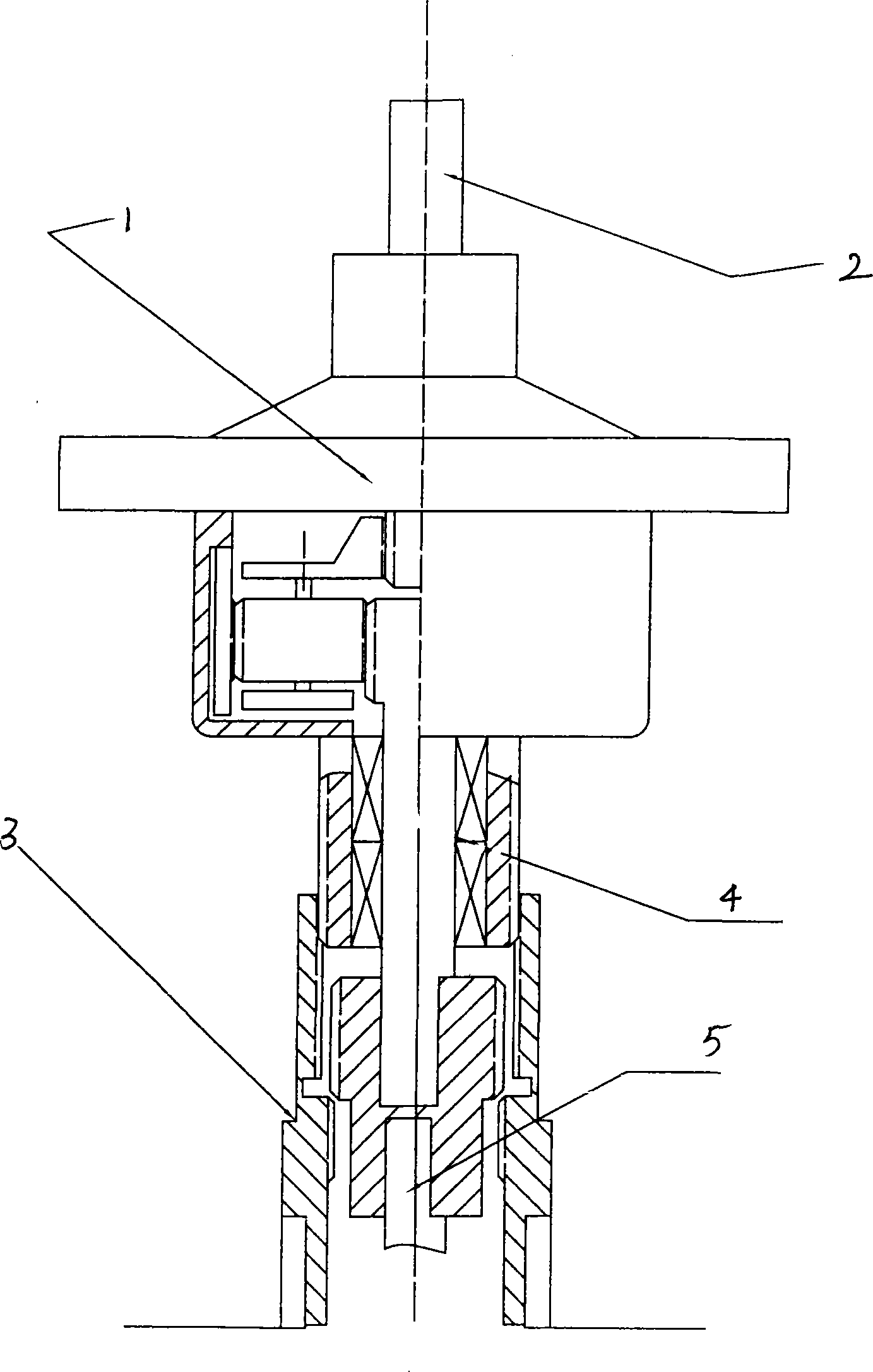
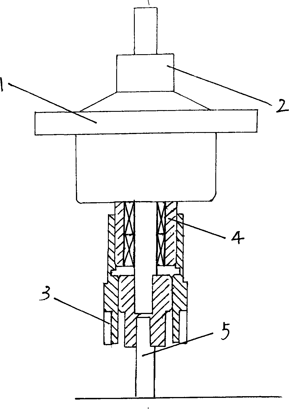
[0015] See attached figure 1 , 2 .

[0016] A novel deceleration clutch device for a washing machine, comprising a decelerator 1, the decelerator 1 having a main output shaft 2, an output bushing 4, and a power input shaft 5, the main output shaft 2 serving as the drive shaft of the pulsator of the washing machine, and the power input A clutch 3 is provided between the shaft 5 and the output shaft sleeve 4. The clutch 3 refers to the clutch gear sleeve. The lower ends of the power input shaft 5 and the output shaft sleeve 4 respectively have external teeth, and the upper and lower ends of the clutch gear sleeve have internal teeth. The clutch gear sleeve can slide up and down under the action of gravity or external force. The clutch gear sleeve slides upward to a certain position, and its upper end meshes with the external teeth on the outer wall of the output shaft sleeve 4, and its lower end engages with the external teeth on the lower end 5 of the power input shaft. At th...


PUM


Abstract

The invention discloses a decelerating clutch device of novel washing machine, which comprises a decelerator, wherein the decelerator is provided with a power input shaft, a main output shaft and an output shaft sleeve. The decelerating clutch device is characterized in that: the main output shaft is used as the driving shaft for impeller of washing machine, a clutch is arranged between the powerinput shaft and the output shaft sleeve and can slide up and down, the clutch can respectively or simultaneously be coupled with the power input shaft and the output shaft bush by the means of mechanical connection. The decelerating clutch device simplifies the structure of the prior decelerating clutch device greatly so as to lower the cost and production processing requirements, besides the decelerating clutch device has simple and convenient structure.

Description

technical field [0001] The invention relates to a deceleration clutch for a washing machine, in particular to a deceleration clutch device for a washing machine that can freely convert speed and torque. Background technique [0002] At present, the known deceleration clutch device of washing machine is realized by deceleration clutch, and it is made up of components such as reduction box, one-way bearing, housing, belt pulley, pulsator shaft, clutch main shaft. When the washing machine needs to achieve speed conversion, it needs to apply a large mechanical force through the traction motor and other external devices to realize the conversion; due to its own composition characteristics, processing requirements and other reasons, at high speed, only one-way high-speed rotation can be realized ; And there are high production and processing requirements, high cost, and complicated use and installation. Contents of the invention [0003] In order to solve the disadvantages of h...

Claims


Application Information

Patent Timeline
Patent Type & Authority Patents(China)
IPC IPC(8): D06F17/08D06F37/30
Inventor 谭江沈剑刘振华王胜杰朱家明王喜雨
Owner HEFEI MIDEA WASHING MACHINE
Why Eureka
Try Eureka