
Installation method of lifting travel locating optoelectronic control device

A technology of photoelectric control and installation method, which is applied in the direction of non-electric variable control, position/direction control, control/regulation system, etc. It can solve the problem of increased damage rate of travel limit position switch, increased equipment failure rate, and no prompt function, etc. Problems, achieve the effect of reducing mechanical loss, low energy consumption, and stable structure

Inactive Publication Date: 2008-09-24
贾广生
View PDF0 Cites 6 Cited by
  • Summary
  • Abstract
  • Description
  • Claims
  • Application Information

AI Technical Summary

Problems solved by technology

[0002] The existing vertical lifting three-dimensional parking equipment uses mechanical travel limit position switches to be installed in different positions. A certain part of the lifting machine directly contacts and collides with the travel limit position switch. The disadvantage is that the lifting machine must Repeated direct contact and collision with the mechanical stroke limit position switch increases the damage rate of the stroke limit position switch, increases the maintenance cost, increases the equipment failure rate, cannot detect empty parking spaces, does not have a prompt function, and is inconvenient to use

Method used


Image

  • Installation method of lifting travel locating optoelectronic control device

Examples


Embodiment 1

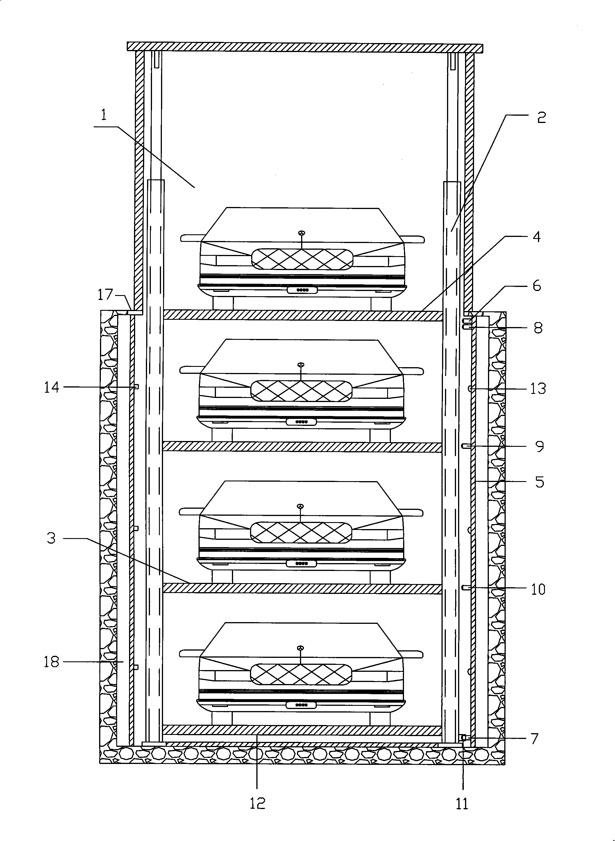
[0022] On the two sides of the three-dimensional vertical lifting parking equipment on the ground floor and underground three floors composed of the parking body 1, the lifting structure body 2, the parking plates 3, and the parking space 4, the two sides of the three-dimensional vertical lifting parking equipment are fixed and installed at the corresponding positions. The upper limit U-shaped photoelectric sensor 6 is installed on the upper side of the functional column 5 corresponding to the ground parking plate 3; the limit positioning U-shaped photoelectric sensor 8 is installed below; the limit positioning is installed at the position corresponding to the lower parking plate 3 U-shaped photoelectric sensor two 9; then install the limit positioning U-shaped photoelectric sensor three 10 at the corresponding position of the lower parking plate; install the lower limit positioning U-shaped photoelectric sensor 7 at the corresponding position under the frame of the bottom parking...

Embodiment 2

[0029]On the two sides of the three-dimensional vertical lifting parking equipment on the ground floor and the underground two floors composed of the parking body 1, the lifting structure body 2, the parking plates 3, and the parking space 4, the two sides of the three-dimensional vertical lifting parking equipment are fixed and installed to stand 5, one The upper limit U-shaped photoelectric sensor 6 is installed on the upper side of the functional column 5 corresponding to the ground parking plate 3; the limit positioning U-shaped photoelectric sensor 8 is installed below; the limit positioning is installed at the position corresponding to the lower parking plate 3 U-shaped photoelectric sensor 2 9; A lower limit positioning U-shaped photoelectric sensor 7 is installed at the corresponding position under the frame of the bottom parking plate 12. Vacancy detection photoelectric sensor transmitters 13 are respectively installed between the two parking panels 3 at positions corresp...

Embodiment 3

[0035] On both sides of the three-dimensional vertical lifting parking equipment on the ground floor and underground floor composed of the parking body 1, the lifting structure body 2, the parking plates 3, and the parking spaces 4, the two sides of the three-dimensional vertical lifting parking equipment corresponding to each other are fixed and installed. The upper limit U-shaped photoelectric sensor 6 is installed on the functional column 5 on the side corresponding to the ground parking plate 3; the limit positioning U-shaped photoelectric sensor 8 is installed below; the lower is installed at the corresponding position under the frame of the bottom parking board 12 Limit positioning U-shaped photoelectric sensor 7. Vacancy detection photoelectric sensor transmitters 13 are respectively installed between the two parking panels 3 at positions corresponding to the car body of the parking space 4; Vacancy detection photoelectric sensor receivers 14 are respectively installed at t...


PUM


Abstract

The invention relates to a mounting method for a lifting stroke location photoelectric control device, in particular to the mounting method for a lifting stroke location photoelectric control device of a solid parking device. The mounting method includes mounting a limitation photoelectric sensor, a limit photoelectric sensor and a detecting photoelectric sensor at the functional upright posts at the two sides of the parking device as well as fixedly connecting a stroke control plate at the frame of a parking plate at the bottom layer. The photoelectric sensor is formed by that a detecting circuit end line is connected with a PLC program controller and a control system as well as a lifting start button; an empty position detecting photoelectric sensor is connected with a signal indicator. The parking body in a sequence from a lower layer parking position to an upper layer parking position is connected with the corresponding lifting start button line of the functional upright post in a sequence from the upper layer limit photoelectric sensor to a lower layer limit photoelectric sensor. A stroke control plate is used for cutting off a photoelectric signal and control the program to realize the lifting stroke location and empty position detecting functions, thus having the advantages of reducing the mechanical loss and the maintenance cost, stable structure, being economic and practical as well as safe and reliable, stable operation, no sound, low cost, low energy consumption and high practicability.

Description

Technical field: [0001] The invention relates to an installation method of a lifting stroke positioning photoelectric control device, in particular to an installation method of a three-dimensional parking equipment lifting stroke positioning empty position detection photoelectric control device, which belongs to the technical field of lifting control. Background technique: [0002] Existing vertical lift type three-dimensional parking equipment stroke lift positioning adopts mechanical stroke limit position switches, which are installed in different positions, and certain parts of the lifting machinery are directly controlled by the collision stroke limit position switch. The disadvantage is that the lifting machinery is certain Repeated parts directly contact and collide with the mechanical stroke limit position switch, which increases the damage rate of the stroke limit position switch, increases the maintenance cost, increases the equipment failure rate, cannot detect empty pa...

Claims


Application Information

Patent Timeline
Patent Type & Authority Applications(China)
IPC IPC(8): E04H6/18G05D3/00E04H6/42
Inventor 贾广生
Owner 贾广生
Learn More