Mud silt blocking method for dilute debris flow and high-sandiness floods and uses thereof
A debris flow and sediment technology, which is applied in excavation, water conservancy projects, climate change adaptation, etc., can solve problems such as unsatisfactory sediment control
- Summary
- Abstract
- Description
- Claims
- Application Information
AI Technical Summary
Problems solved by technology
Method used
Image
Examples
Embodiment 1
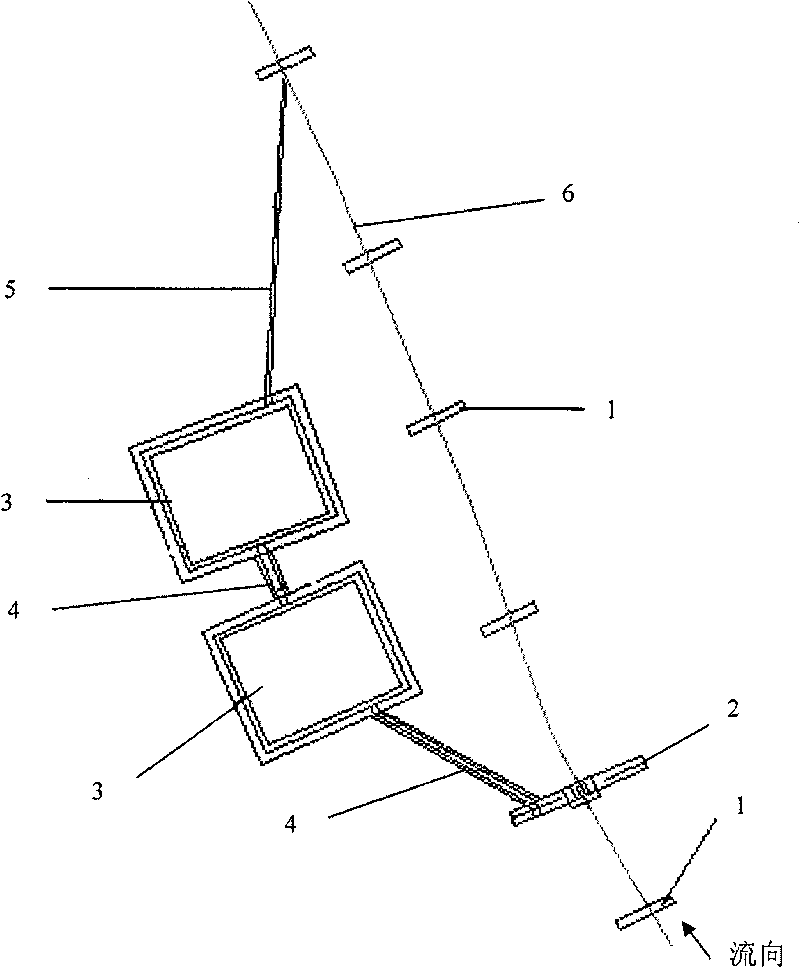
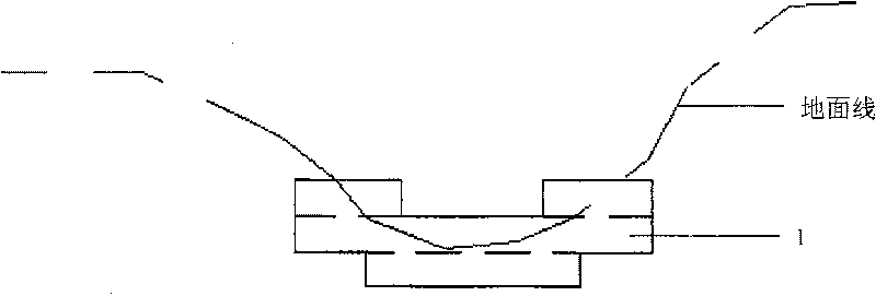
[0029] like figure 1 , figure 2 , image 3 , Figure 4 , Figure 5 , Image 6 shown. For a watershed area of 1.0km 2 , The vegetation coverage rate is 40%, the slope of the accumulation fan is 15%, and the clay content in the accumulation particles on the accumulation fan is 4% in the debris flow area. Fine-grained matter from dilute debris flows and sediment from high-sediment floods. Several lead wire cage bed dams 1 for stabilizing the quality of the main ditch bed are provided in the main ditch bed 6, and the main ditch bed 6 is fixed in sections. In the upstream of the main ditch bed 6, there is a gravity drainage valley square 2 for drainage, and on the side of the main ditch bed 6 downstream of the gravity drainage valley square 2, there are two parallel to the main ditch bed 6 and along the main ditch. The lead wire cage grit chamber 3 connected in series with the drainage ditch 4 in the direction of the bed 6; the gravity drainage valley 2 is connected with...
Embodiment 2
[0032] like figure 1 , figure 2 , image 3 , Figure 4 , Figure 5 , Image 6 shown. For a watershed area of 2.0km 2, In the debris flow area where the vegetation coverage rate is 40%, the slope of the accumulation fan is 20%, and the clay content of the accumulated particles on the accumulation fan is 6%, two backbone sand check dams with an effective dam height of 7m are installed on the top of the accumulation fan. At the same time, use the following sediment retention method on the main ditch bed to intercept the fine particles of dilute debris flow and the sediment of high-sediment flood. Several lead wire cage bed dams 1 for stabilizing the quality of the main ditch bed are provided in the main ditch bed 6, and the main ditch bed 6 is fixed in sections. In the upstream of the main ditch bed 6, there is a gravity drainage valley square 2 for drainage, and on the side of the main ditch bed 6 downstream of the gravity type drainage valley square 2, there are 3 par...
Embodiment 3
[0035] like figure 1 , figure 2 , image 3 , Figure 4 , Figure 5 , Image 6 shown. The same place as in Embodiment 1 will not be described again, and the difference is that:
[0036] The drainage area is 0.8km 2 , The slope of the accumulation fan is 10%. The depth of the lead wire cages embedded in the lead wire cage bed dam 1 on both sides of the main ditch bed 6 is 0.5m; the distance between the lead wire cage bed dams 1 is 15.0m, and the size of the lead wire cages in the lead wire cage bed dam 1 is 2.0 m×0.5m×0.5m. The quantity of the lead wire cage grit chamber 3 is one, the size is 4.0m×10.0m, and the depth is 2.0m. The foundation of gravity drainage Gufang 2 is buried at a depth of 1.0m, the foundation is a concrete structure, the effective height of the dam body is 1.5m, the width of the dam crest is 0.4m, the slope of the downstream side of the dam body is 1:0.05, and the slope of the upstream side is 1:0. 0.4, the dam structure is concrete.
PUM
 Abstract
Description
Claims
Application Information
 - R&D
- Intellectual Property
- Life Sciences
- Materials
- Tech Scout
- Unparalleled Data Quality
- Higher Quality Content
- 60% Fewer Hallucinations
Browse by: Latest US Patents, China's latest patents, Technical Efficacy Thesaurus, Application Domain, Technology Topic, Popular Technical Reports.
© 2025 PatSnap. All rights reserved.Legal|Privacy policy|Modern Slavery Act Transparency Statement|Sitemap|About US| Contact US: help@patsnap.com


