Roller skate

A roller-skating and wheel-type technology, which is applied to roller-skating shoes, skating, skateboards, etc., can solve the problems of no longer being used, single-row roller shoes are not being used, etc., and achieve the effect of improving traveling comfort.

Inactive Publication Date: 2008-09-17
赫尔穆特・阿贝尔
View PDF6 Cites 3 Cited by
  • Summary
  • Abstract
  • Description
  • Claims
  • Application Information

AI Technical Summary

Problems solved by technology

[0011] It can thus be ascertained that although millions of these inline skates have been sold to athletes of all ages during this period, most of these inline skates are either not in use or are no longer in use, probably due to this problem

Method used


Image

  • Roller skate
  • Roller skate
  • Roller skate

Examples


Embodiment Construction

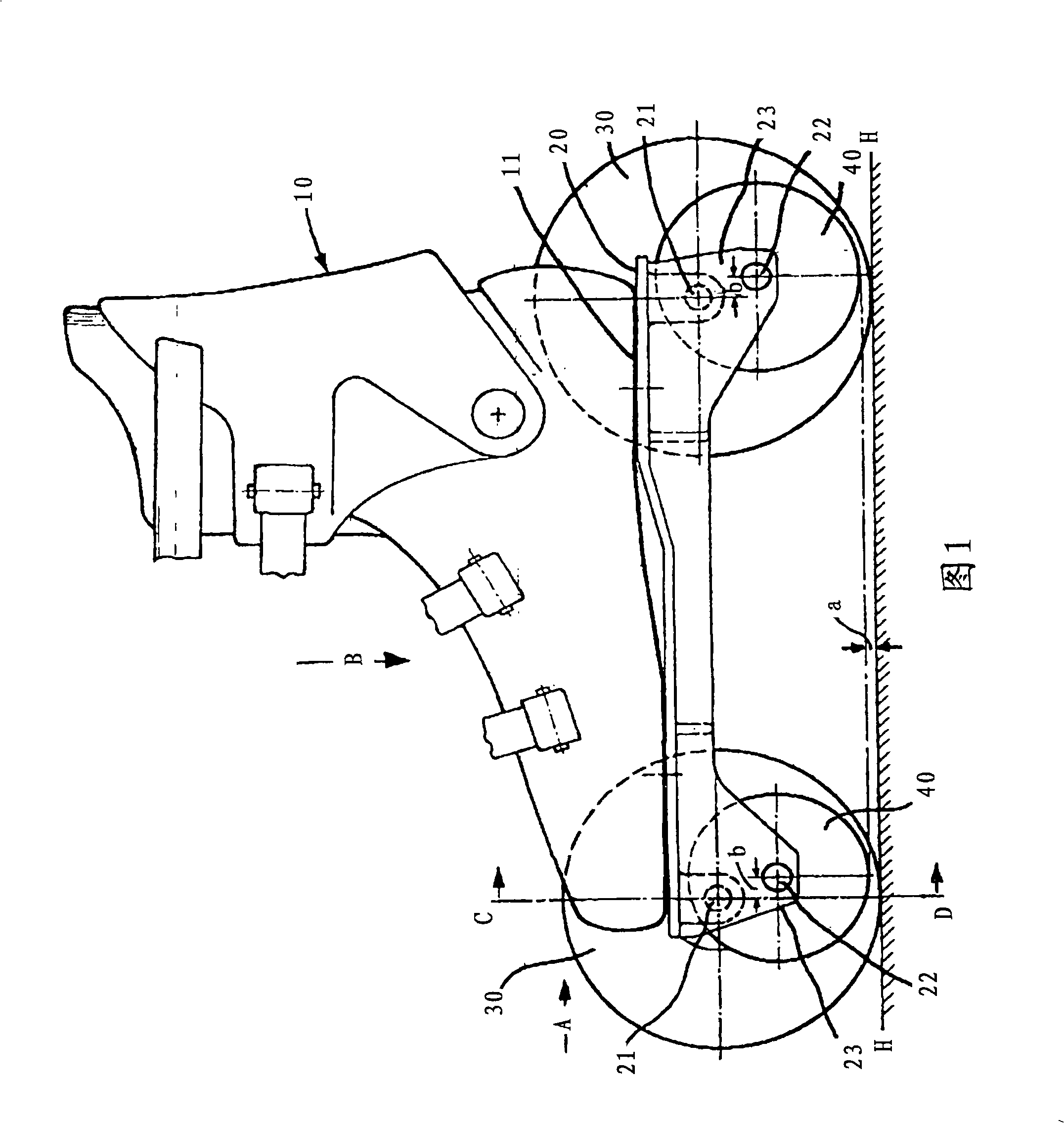
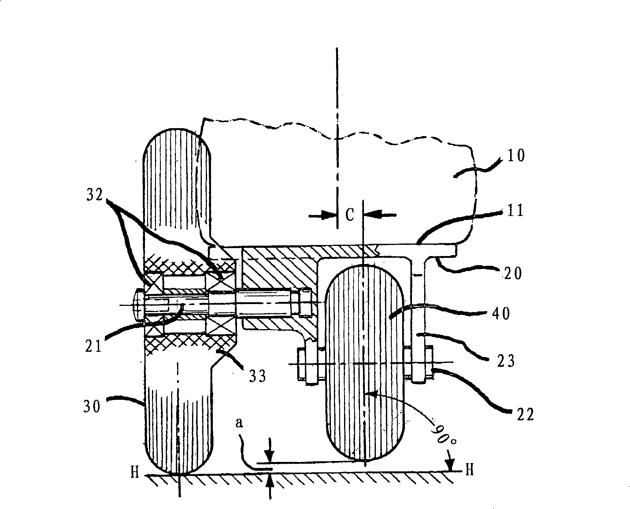
[0029] The invention is illustrated by means of the roller skate on the right side of the pair of roller skates, which is illustrated in FIGS. Figure 5 are shown in different positions.

[0030] The roller skate basically comprises a boot 10, on the sole 11 of which a frame 20 with pulleys 30 and 40 is fastened as a pulley bearing element. The roller skate on the left (not shown) is designed mirror-symmetrically. The pulley 30 of larger size stands vertically in this view on the raceways H-H. They are always located on the outside of the roller skate. A smaller sized pulley 40, which is similarly located below the boot 10 as in an inline shoe and referred to below as an inline pulley, is shown in FIGS. figure 2 The position shown in is maintained at a distance a from the surface of the raceway H-H.

[0031] In the exemplary embodiment shown in FIGS. 1 to 3 , the rear outer pulley 30 is larger and wider than the front pulley.

[0032] The frame 20 , made of aluminum die-c...


PUM


Abstract

The roller skate according to the invention is equipped with smaller inline rollers (40) arranged below the boot (10) and with outer, larger rollers (30), the upper parts of which protrude above the boot sole (11). This roller skate can be moved on four rollers (30) and (40) in the manner of a four-wheel roller skate, or, in certain phases, just on two inline rollers (40) in a similar manner to an inline skate.

Description

technical field [0001] The invention relates to a roller skate of the type stated in the preamble of claim 1 . Background technique [0002] Roller skates are known which have four pulleys arranged in pairs and a plurality of pulleys arranged in a row one behind the other, so-called inliners and hybrids. [0003] The most familiar are four-wheeled roller skates, which are generally provided with four generally relatively wide, mostly cylindrical, wheels of the same diameter. When traveling, such roller skates are usually placed on the running track as horizontally as possible with all four pulleys at the same time. [0004] The sole of such four-wheel skates with limited steerable front and rear pulleys is relatively low in the heel area, so that the user can bend his legs sideways in the area above the foot joint. The limited steerable front and rear pulleys of the four-wheeled roller skate can thus be controlled via the tilted position of the legs. An inclined position ...

Claims


Application Information

Patent Timeline
Patent Type & Authority Applications(China)
IPC IPC(8): A63C17/06
CPCA63C17/06A63C17/004A63C17/006A63C17/0073A63C17/04
Inventor 赫尔穆特·阿贝尔O·德阿塞勒尔C·阿贝尔D·阿贝尔
Owner 赫尔穆特・阿贝尔
Why Eureka
Try Eureka