
Heat exchanger and washing apparatus comprising the same

A technology for cleaning devices and heat exchangers, which is applied in the direction of cleaning heat transfer devices, water supply devices, water heaters, etc., and can solve problems such as cleaning nozzle clogging, difficulty in miniaturization of heat exchangers, and difficulty in miniaturization of sanitary cleaning devices. Reduce the adhesion of impurities, prevent or reduce adhesion, and improve the effect of heat exchange efficiency

Inactive Publication Date: 2008-09-17
PANASONIC CORP
View PDF7 Cites 8 Cited by
  • Summary
  • Abstract
  • Description
  • Claims
  • Application Information

AI Technical Summary

Problems solved by technology

However, in the existing heat exchanger, impurities such as scale will accumulate due to long-term use.
Therefore, when a large amount of foreign debris attached to the heat exchanger is discharged from the heat exchanger, it will cause clogging of the cleaning nozzle, so that the cleaning water cannot be sprayed.
As a result, the life of the sanitary cleaning device is shortened
[0010] In addition, since it is difficult to miniaturize the existing heat exchanger, it is also difficult to miniaturize the sanitary cleaning device using the heat exchanger.

Method used


Image

  • Heat exchanger and washing apparatus comprising the same
  • Heat exchanger and washing apparatus comprising the same
  • Heat exchanger and washing apparatus comprising the same

Examples


Embodiment Construction

[0202] Embodiments of the present invention will be described below with reference to the drawings. However, the present invention is not limited to these embodiments.

[0203] (first embodiment)

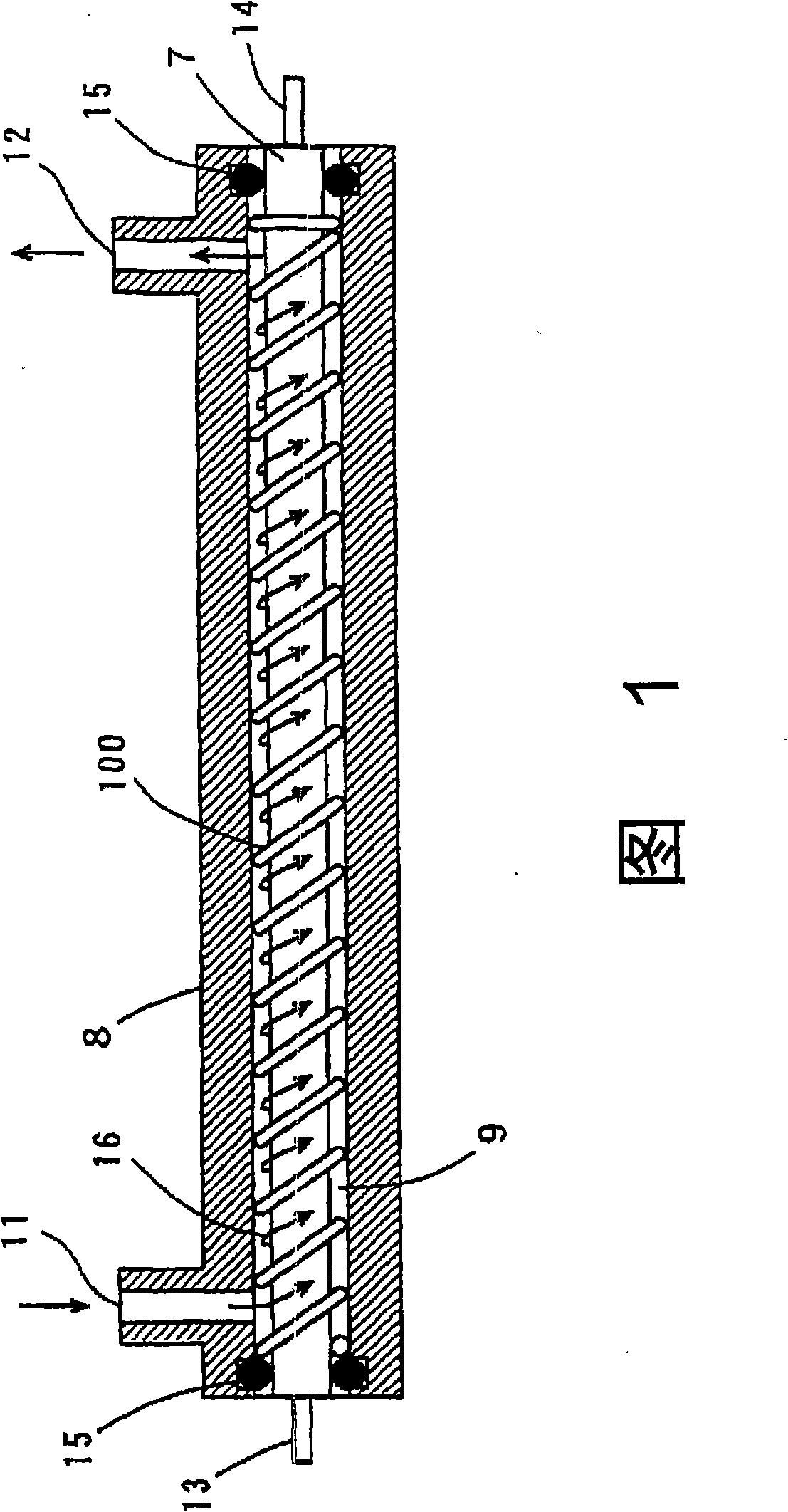
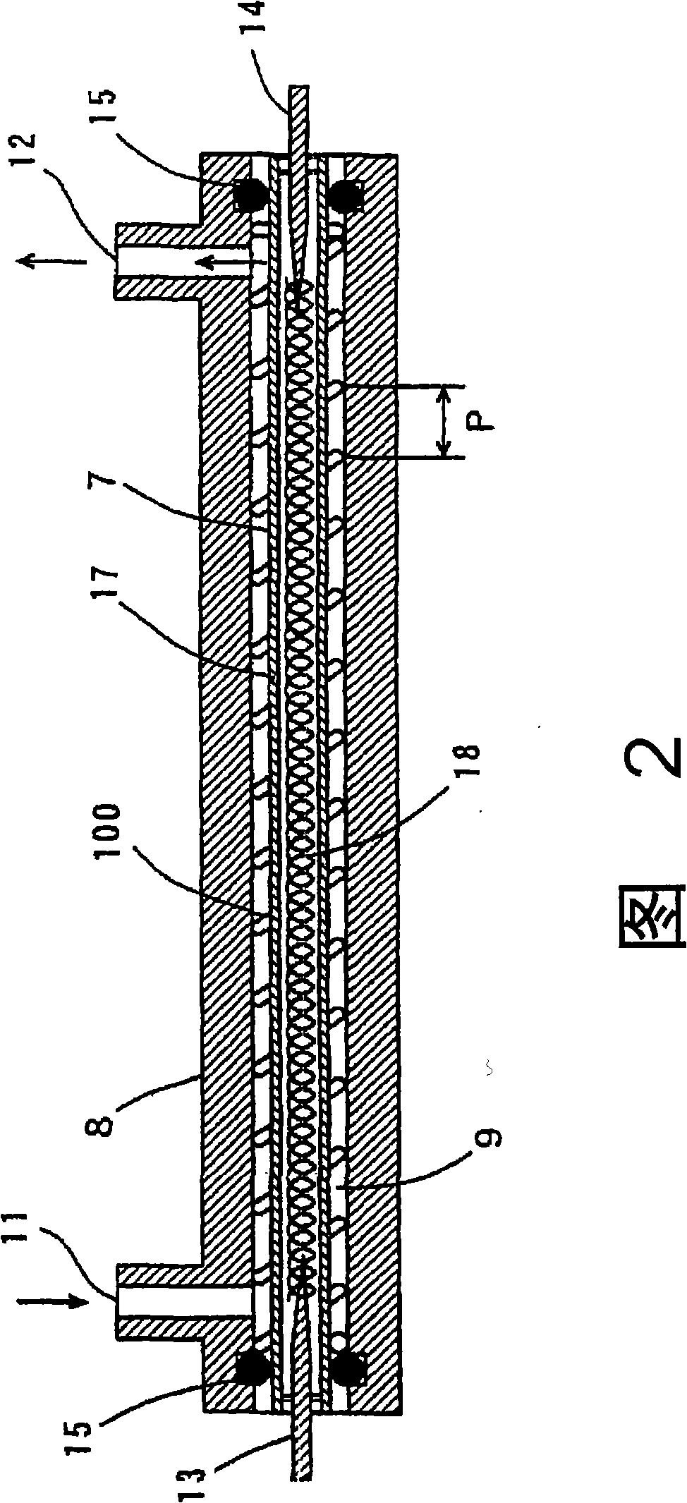
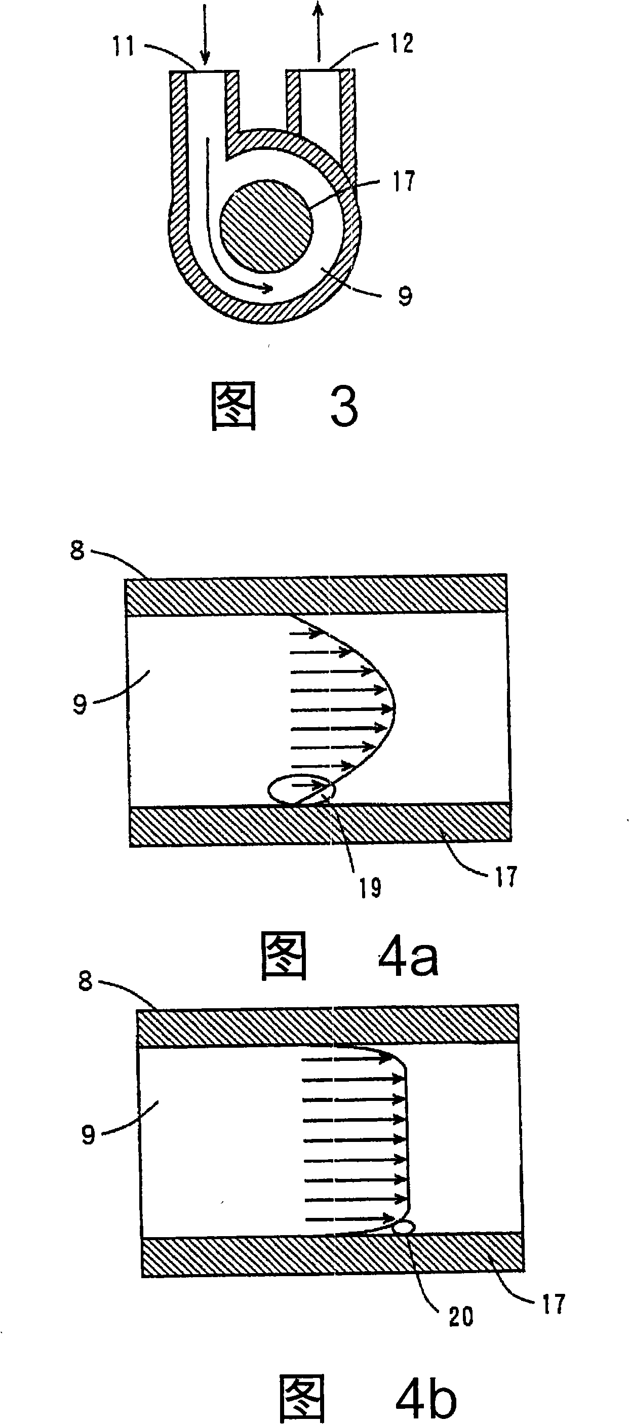
[0204]1 and 2 are axial cross-sectional views of a heat exchanger according to a first embodiment of the present invention. FIG. 1 shows a section of a casing and a side surface of a sheath heater, and FIG. 2 shows a section of the casing and the sheath heater. Fig. 3 is a transverse cross-sectional view of the heat exchanger shown in Figs. 1 and 2 .

[0205] In FIG. 1 , the heat exchanger is composed of a substantially cylindrical sheath heater 7 , a substantially cylindrical housing 8 and a coiled spring 100 . The sheath heater 7 is a heating element for heating water as a fluid, and is accommodated in the case 8 . The casing 8 has a hollow with a circular or elliptical cross section, and is provided to surround the outer periphery of the sheath heater 7 . The spring 100 is pr...


PUM


Abstract

A heat exchanger is constituted of a substantially circular cylindrical sheathed heater, a substantially circular cylindrical case, and a spiral spring. The sheathed heater is received in the case, and the spring is wound on the outer peripheral surface of the sheathed heater. Thus, a spiral flow path is formed in a space surrounded by the outer peripheral surface, inner peripheral surface of the case, and spring. The spring functions as a flow speed changing mechanism, turbulence producing mechanism, flow direction changing mechanism, and impurity removing mechanism. A water inlet and a water outlet are arranged on a side surface of the case, at positions eccentric from the center axis of the case.

Description

[0001] The patent application of the present invention is the international application number PCT / JP2004 / 018389, the international application date is December 9, 2004, the application number entering the Chinese national stage is 200480036062.2, and the name is "Heat exchanger and cleaning machine with the heat exchanger Device" is a divisional application of the invention patent application. technical field [0002] The invention relates to a heat exchanger for heating fluid and a cleaning device with the heat exchanger. Background technique [0003] In a sanitation washing device for washing parts of the human body, a clothes washing device for washing clothes, and a dish washing device for washing dishes, a heat exchanger for heating water is used (for example, refer to Patent Document 1 ). [0004] Fig. 48 is a schematic sectional view of a conventional heat exchanger. As shown in FIG. 48 , this heat exchanger has a double-tube structure composed of a cylindrical bas...

Claims


Application Information

Patent Timeline
Patent Type & Authority Applications(China)
IPC IPC(8): F28G9/00E03D9/08F24H1/16F24H9/00F28F1/40
CPCY02B40/44
Inventor 白井滋梅景康裕中村一繁古林满之安井圭子冈浩二
Owner PANASONIC CORP
Learn More