
Safety alarm device for flat knitting machine

A safety alarm device and the technology of knitting flat knitting machines, which are applied in knitting, textiles and papermaking, etc., can solve the problems of inability to generate alarms, affect the performance of fabric weaving machines, and achieve the effect of improving weaving quality

Active Publication Date: 2008-09-10
NINGBO CIXING
View PDF0 Cites 6 Cited by
  • Summary
  • Abstract
  • Description
  • Claims
  • Application Information

AI Technical Summary

Problems solved by technology

At present, the most common probe device in the field of flat knitting machines has a left and right swing type probe piece. When the machine head is running, the probe device only alarms the abnormal yarn and sundries in front of it (ie left or right). Since the probe sheet can only swing left and right, it cannot detect abnormal floating yarns and sundries in the vertical direction, and thus cannot generate an alarm, which greatly affects the weaving effect of the fabric and the performance of the machine. Therefore, The invention provides a new type of safety alarm device for probes. When the device is working, the probe piece can not only swing left and right, but also swing up and down, which plays a good role in protecting fabrics and machines and greatly improves the safety of fabrics. Weaving quality and machine life

Method used


Image

  • Safety alarm device for flat knitting machine
  • Safety alarm device for flat knitting machine

Examples


Embodiment Construction

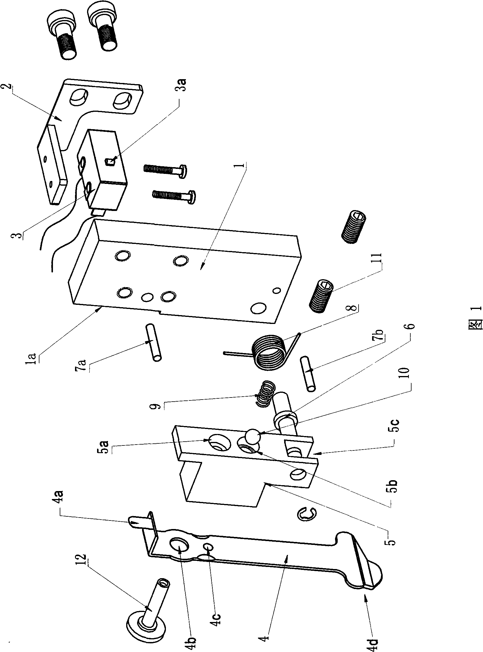
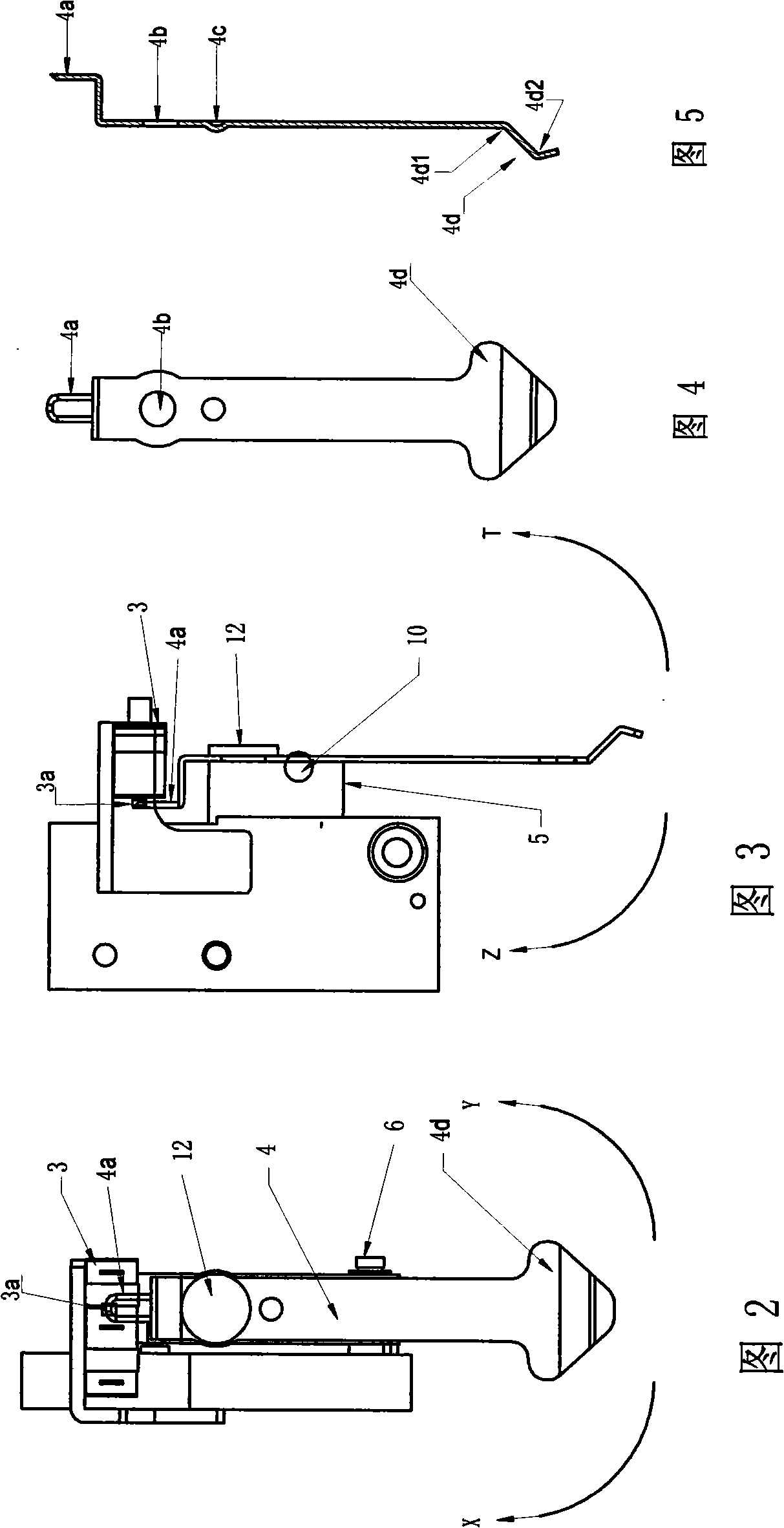
[0017] As shown in Figure 1, Figure 2, and Figure 3, the upper end of the probe base 1 is equipped with a micro switch base 2, and the micro switch 3 is fixed on the micro switch base 2 and placed on the front of the probe base 1. The contacts 3a on the top face the front side 1a of the probe holder. Two limit pins are provided on the side of the probe base, namely the first limit pin 7a and the second limit pin 7b.

[0018] The lower end of the probe holder 5 is provided with a slot 5c, and a torsion spring 8 is installed in the slot 5c, and the rotating shaft 6 passes through the torsion spring 8 to rotatably connect the probe holder 5 to the lower end side of the probe holder 1 . Both ends of the torsion spring 8 are fixed on the probe base through the first limiting pin 7a and the second limiting pin 7b. In this way, the probe frame 5 can swing up and down relative to the probe holder, that is, it can swing along the Z and T directions. Due to the limiting effect of the t...


PUM

PropertyMeasurementUnit
Bending angleaaaaaaaaaa

Abstract

The invention relates to the flat knitting machine technical field, in particular to a safety alarm device for a flat knitting machine, which is positioned on one end of a handpiece near to a neilsbed. The safety alarm device comprises a probe, a probe seat and a microswitch, wherein the probe connected on the probe seat matches the microswitch fixed on the probe seat. The safety alarm device is characterized in that: the safety alarm device also comprises a probe carriage, the probe is in transmission connection with the front of the probe carriage through a shaft pin, the side of the probe carriage is in transmission connection with the probe seat through a rotating shaft, and the axial direction of the rotating shaft is mutually vertical to the axial direction of the shaft pin. The lower end of the probe carriage is provided with a grooving; the rotating shaft horizontally drills through the grooving and is in transmission connection on the probe seat, a torsional spring is sleeved on the rotating shaft, the main body of the torsional spring is positioned in the grooving, and two ends of the torsional spring are fixed on the probe seat. The safety alarm device for the flat knitting machine provides multi-position safe warning for the flat knitting machine, and has better protection to fabrics and the machine.

Description

technical field [0001] The invention relates to the technical field of flat knitting machines, in particular to a safety alarm device for the flat knitting machine used when the flat knitting machine knits garment parts. Background technique [0002] The safety alarm device used on the flat knitting machine is the probe device. When the machine is knitting garment pieces, the probe device will give a safety alarm to abnormal conditions such as yarn floating, flying yarn and sundries blocking, so as to prevent the knitting breakage or other malfunction of the machine occurs. At present, the most common probe device in the field of flat knitting machines has a left and right swing type probe piece. When the machine head is running, the probe device only alarms the abnormal yarn and sundries in front of it (ie left or right). Since the probe sheet can only swing left and right, it cannot detect abnormal floating yarns and sundries in the vertical direction, and thus cannot gen...

Claims


Application Information

Patent Timeline
IPC IPC(8): D04B35/10
Inventor 孙平范
Owner NINGBO CIXING
Learn More