
Accumulator charging circuit in solar lighting system

A lighting system and charging circuit technology, which is applied to battery circuit devices, circuit devices, collectors, etc., can solve the problems of large charging current and damage to the battery, and achieve the effect of preventing large current impact and prolonging the service life

Inactive Publication Date: 2008-08-13
上海秋闻电子有限公司
View PDF0 Cites 0 Cited by
  • Summary
  • Abstract
  • Description
  • Claims
  • Application Information

AI Technical Summary

Problems solved by technology

But such a circuit has the safety of battery charging, because the best charging process of the battery is the transition from constant current to constant voltage. The charging current may damage the battery

Method used


Image

  • Accumulator charging circuit in solar lighting system
  • Accumulator charging circuit in solar lighting system

Examples


Embodiment Construction

[0011] Below in conjunction with accompanying drawing and specific embodiment the present invention is described in further detail:

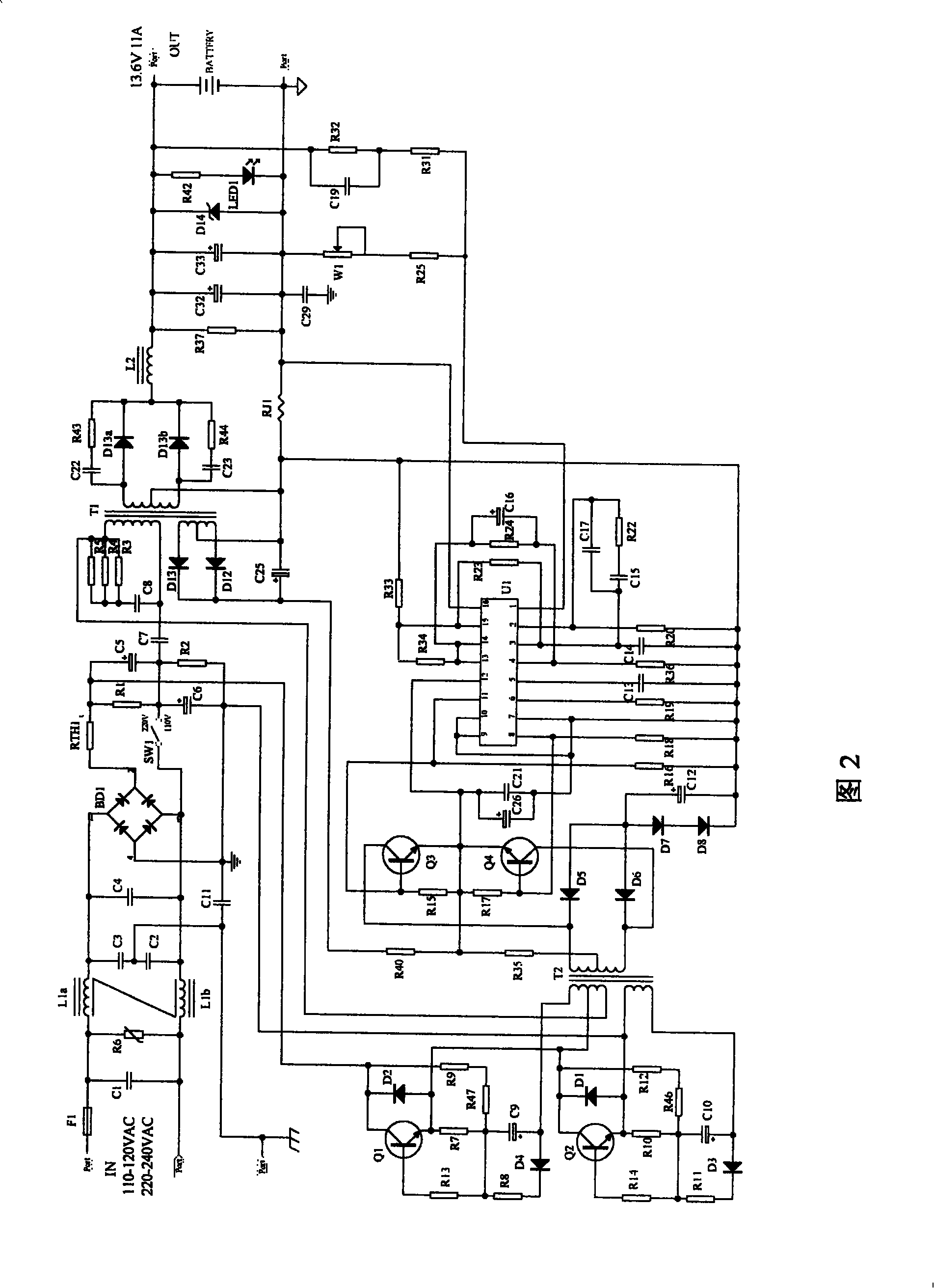
[0012] It can be seen from Fig. 2 that the present invention includes: pulse width modulation control chip U1, the first main power transformer T1; also includes: charging current sampling resistor RJ1, amplifier feedback resistor: twenty-third resistor network R23; pulse width modulation control chip U1 Inverting terminal resistance: the thirty-third resistor network R33, the thirty-fourth resistor network R34; one end of the charging current sampling resistor RJ1 is connected to the ground winding of the first main power transformer T1, and the other end is respectively connected to the negative pole of the storage battery Connected to pin 16 of the non-inverting terminal of the pulse width modulation control chip U1; one end of the twenty-third resistor network R23 is connected to the 15th pin of the pulse width modulation control chip U1, and...


PUM


Abstract

The invention relates to a charging circuit for the storage battery of a solar energy illumination system, comprising: a pulse width modulating control chip, a first main power transformer, also comprising: one end of a sampling resistance for charging current is connected with the grounded winding of the main power transformer, the other end of the sample resistance is connected with the negative pole of the storage battery and the same phase end sixteenth pin of the pulse width modulating control chip respectively; one end of the twenty third resistance network is connected with the fifteenth pin of the pulse width modulating control chip, the other end of the twenty third resistance network is connected with the third pin of the pulse width modulating control chip; one end of the thirty third resistance network is connected with the grounded end of the first main power transformer, the other end of the thirty third resistance network is connected with the fifteenth pin of the pulse width modulating control chip; the two ends of the thirty forth resistance network are connected with the fifteenth pin and the fourteenth pin of the pulse width modulating control chip respectively; because a constant current / constant voltage charging mode autochangeover is adopted, so that high current surge is prevented, the lifetime of the storage battery is prolonged.

Description

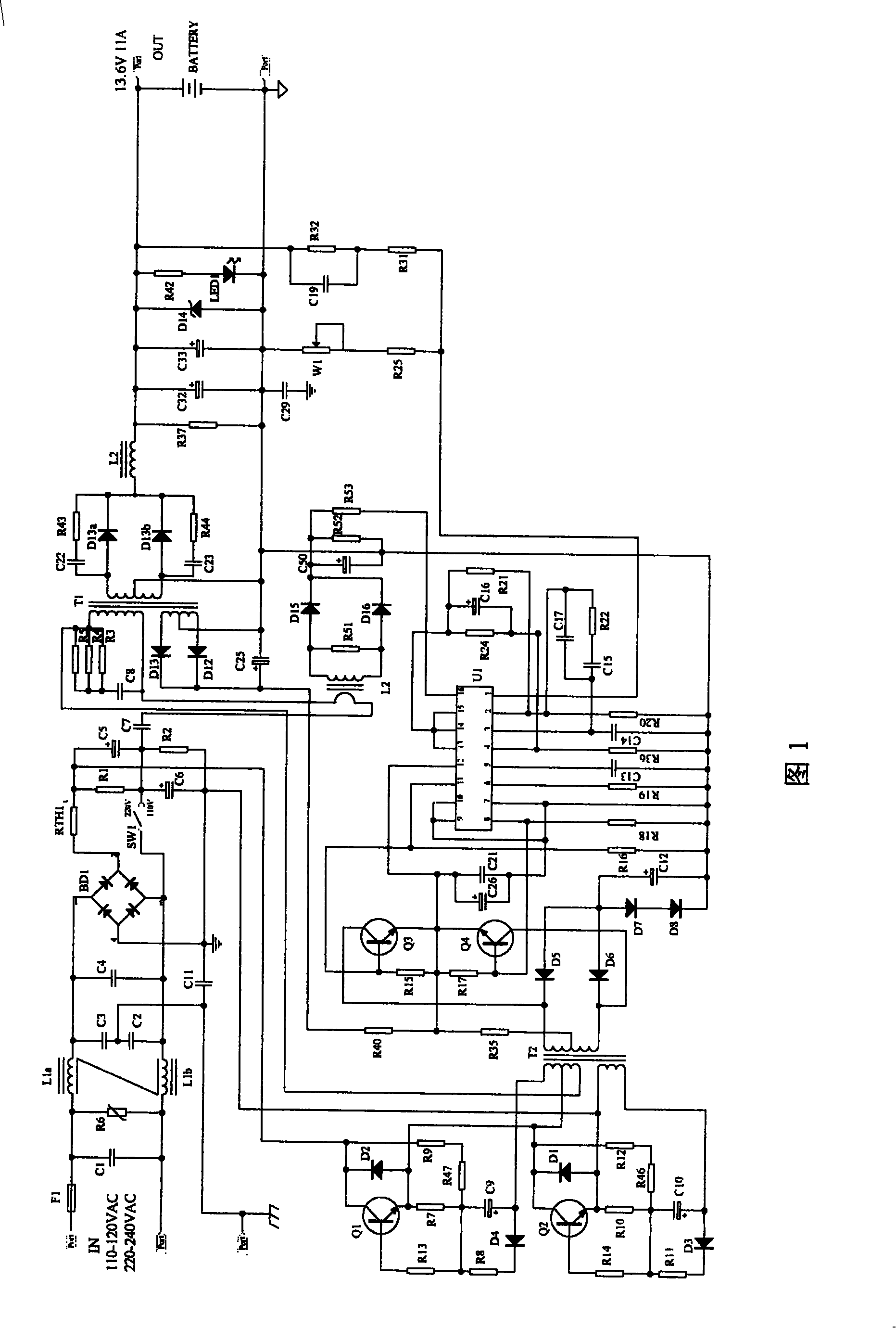
technical field [0001] The invention relates to a storage battery in a solar lighting system, in particular to a charging circuit for the storage battery. Background technique [0002] In a solar lighting system, the solar cell converts sunlight into electrical energy and stores it in the battery, and then supplies the electrical energy in the battery for lighting at night, and completes this conversion over and over again. However, in practical applications, when there is insufficient sunshine in continuous rainy days, the solar battery cannot provide enough electric energy to charge the battery, and the battery is insufficiently charged. Damage, which is a practical problem in solar lighting applications. [0003] It can be seen from Figure 1: it is the basic circuit structure of DC stabilized voltage power supply. The circuit is a 150W charger with an input of 220VAC, an output of 13.6VDC, and a maximum charging current of 10A. In the application of solar supplementary...

Claims


Application Information

Patent Timeline
Patent Type & Authority Applications(China)
IPC IPC(8): H02J7/35H02J7/00
Inventor 吴秋闻
Owner 上海秋闻电子有限公司
Learn More