Appliance for knee joint varus and valgus deformity
A technology for valgus deformity and knee joints, applied in valgus deformity correctors, adjustable knee joints, and knee joints, which can solve the problems of long bed rest, high cost, and great pain, and achieve easy wearing and simple structure Effect
- Summary
- Abstract
- Description
- Claims
- Application Information
AI Technical Summary
Problems solved by technology
Method used
Image

Examples
Embodiment 1
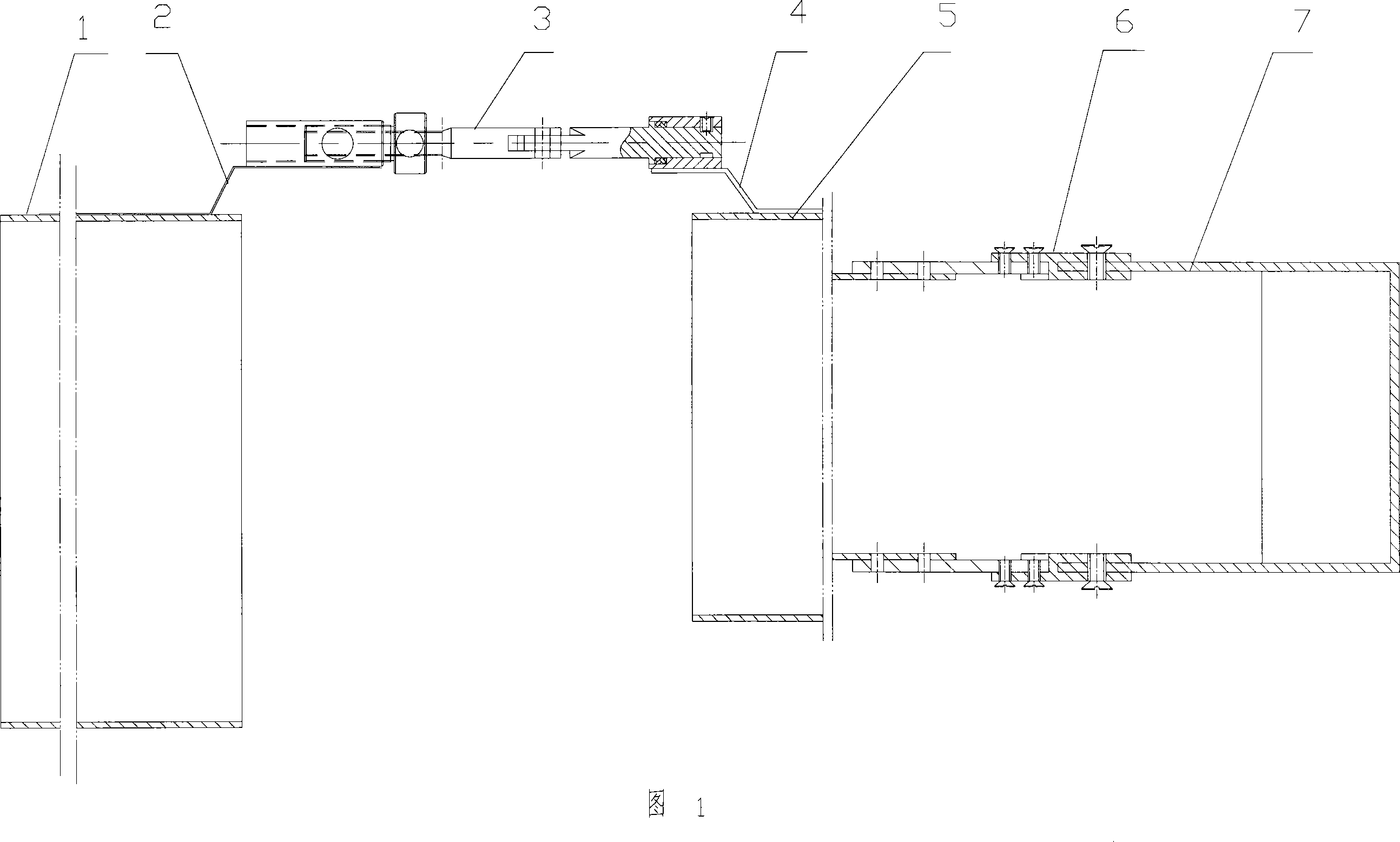
[0021] With reference to accompanying drawings 1 and 2 of the description, the knee joint varus and valgus deformity corrector of the present invention includes a thigh collar 1 and a calf collar 5, and is arranged on the inside of the leg, and is connected to the thigh collar through connecting plates 2 and 4 respectively. 1 and the universal joint 3 that is tightly connected with the calf hoop 5, and the foot hoop 7 that is connected with the calf hoop through the connecting plate 6. The above-mentioned connecting plate is made of stainless steel plate, and its strength is mainly considered. Using a high-strength steel plate can achieve a smaller size and meet the required strength requirements, and also make the structure of the aligner more compact.
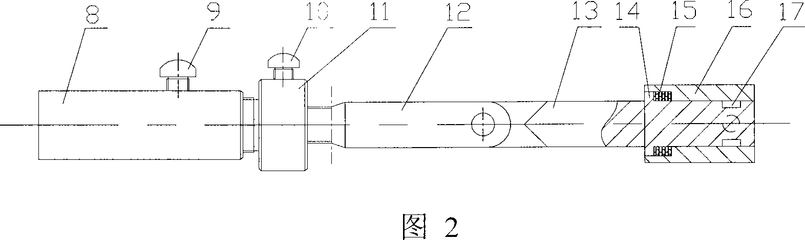
[0022] Among them, the universal joint includes a steel cylinder 8 welded to the connecting plate 2 and has an internal thread, a steel cylinder 11 threaded with the steel cylinder, a connecting rod 12 threaded with the steel ...
Embodiment 2
[0028] With reference to accompanying drawings 1 and 2 of the description, this implementation ideally should be in accordance with embodiment 1, the main difference is that it is applied to the situation where there is a damaged surface in the outer joint of the knee varus or valgus deformity, that is, the universal joint 3 is set on the outer side of the right leg . Considering the manufacturing cost simultaneously, adopt thigh hoop 1, shank hoop 2 front sides to be provided with a long strip hole, its inner side is provided with evenly distributed sponge or cotton lining. There is a 4cm margin for the thigh cuff and the calf cuff corresponding to the physiological structure of the human body. In fact, the larger the margin, the easier it is to wear, but it will have an adverse effect on the binding, that is, to balance the resilience of the base of the leg sleeve, a greater binding force is required. The maximum size is 5cm. If it is too large, the binding force required w...
Embodiment 3
[0030] Refer to Figures 1 and 2 of the instruction manual. In fact, in order to obtain a more ideal correction effect, no matter whether the articular surface is damaged on the side of the knee varus or valgus deformity, if a universal joint 3 is installed on the inner and outer sides of the leg, it will be more effective. Good results. One is that the whole orthotic has high structural strength and good stability due to the adoption of two universal joints, and the adjustment is more convenient. For situations where the entire articular surface is damaged, this is an inevitable choice in the present invention.
PUM
 Abstract
Description
Claims
Application Information
 - Generate Ideas
- Intellectual Property
- Life Sciences
- Materials
- Tech Scout
- Unparalleled Data Quality
- Higher Quality Content
- 60% Fewer Hallucinations
Browse by: Latest US Patents, China's latest patents, Technical Efficacy Thesaurus, Application Domain, Technology Topic, Popular Technical Reports.
© 2025 PatSnap. All rights reserved.Legal|Privacy policy|Modern Slavery Act Transparency Statement|Sitemap|About US| Contact US: help@patsnap.com