
Spiral gunlock device

A locking mechanism and bolt technology, which is applied in breech mechanism, weapon accessories, offensive equipment, etc., can solve the problems of sealing effect, simplicity, choice and incompatibility of bolt and bolt, and achieve the effect of simple structure, good effect, and improved shooting accuracy

Inactive Publication Date: 2008-08-06
吴云锋
View PDF1 Cites 1 Cited by
  • Summary
  • Abstract
  • Description
  • Claims
  • Application Information

AI Technical Summary

Problems solved by technology

In order to solve the sealing problem of the combustion chamber, there are many solutions in the existing technology, but there is a trade-off between the sealing effect and the simplicity of the bolt.

Method used


Image

  • Spiral gunlock device
  • Spiral gunlock device
  • Spiral gunlock device

Examples


Embodiment Construction

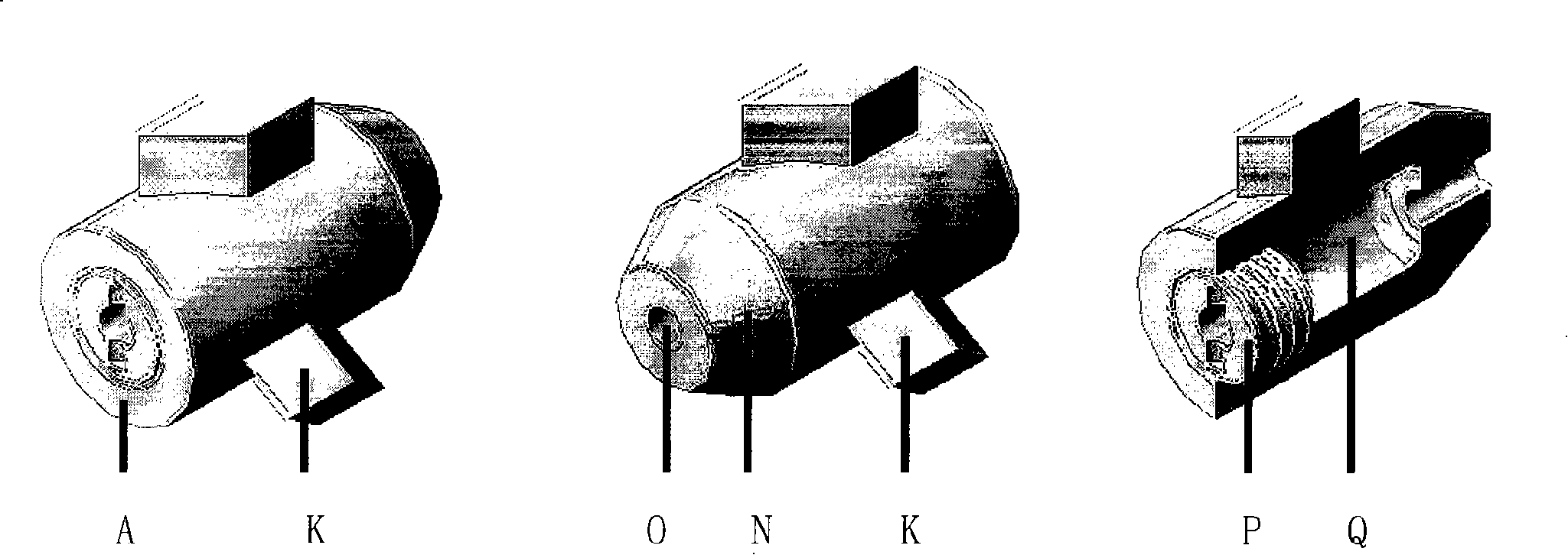
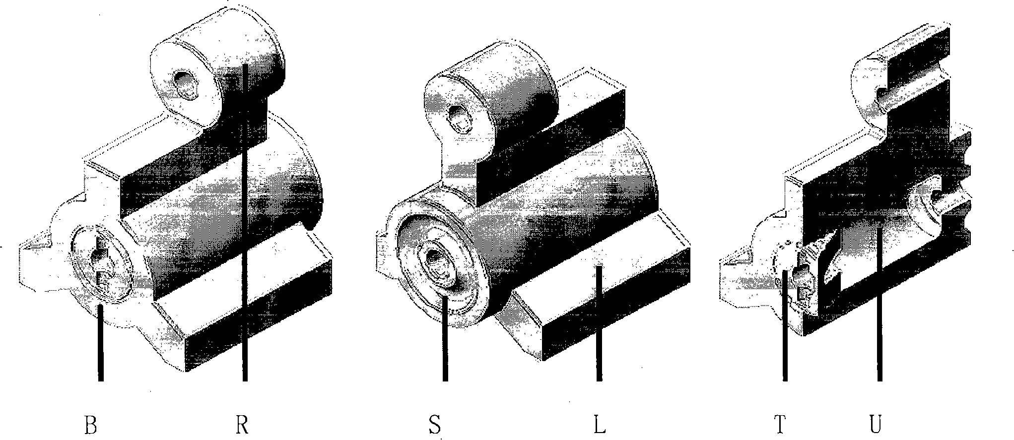
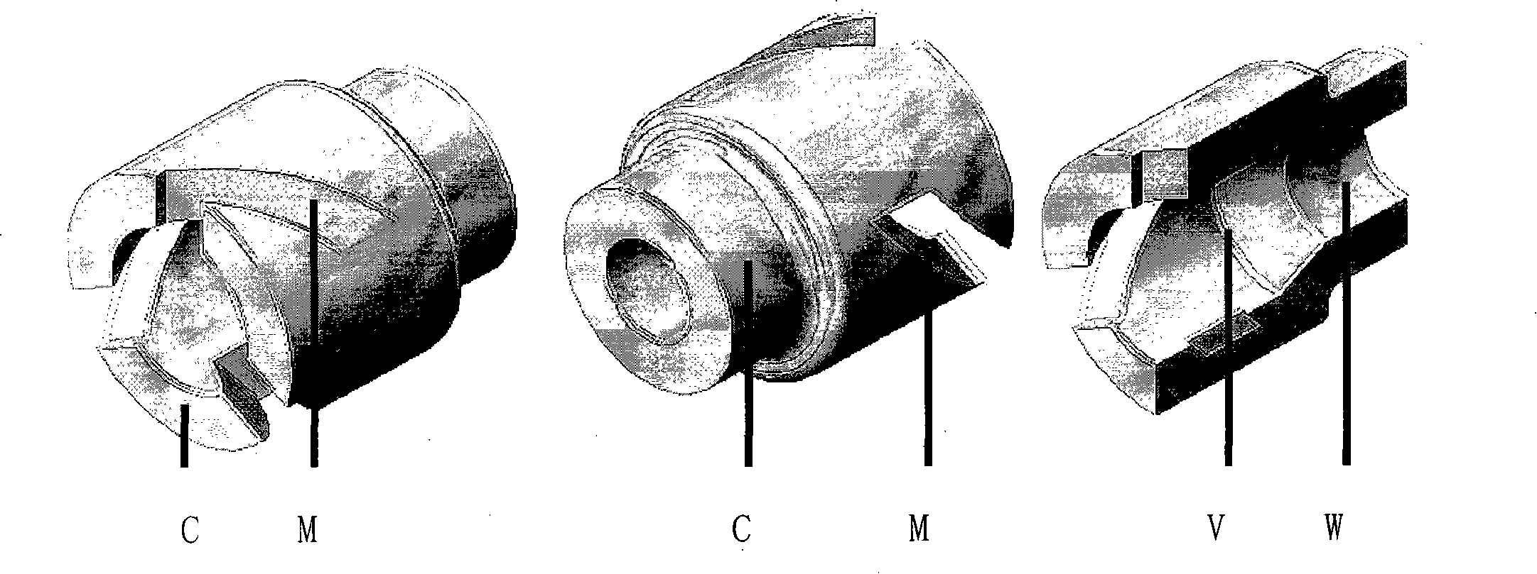
[0046] When the first round is loaded, the charging handle E is pulled, the charging handle E forces the bolt seat B to move backward, the bolt seat B moves back through the striker D and the striker spring G together with the bolt A, and the bolt is unlocked (attached Figure 5 ). The gun bolt overwhelms the hammer and pulls the bullet bar to pull the ammunition out of the magazine. Let go of the charging handle, the recoil spring F works to push the bolt back, and the bolt A pushes the ammunition removed from the magazine into the chamber, and at the same time, it should be guided by the guide groove M of the barrel assembly to rotate and lock (attached Figure 8). The hammer hits the firing pin D to trigger the ammunition. Instantaneously due to the "Bushley's Law" the bolt A sticks to the barrel assembly C, and the breech pressure drops, the bolt A and the barrel assembly C move relative to each other, and the bolt unlocks. Compared with the first round of unlocking, the...


PUM


Abstract

The invention relates to an action mechanism of a light fuel weapon, which is characterized of briefness. The principle is that two objects two inclined surfaces (under the condition of opposite moving direction) of which are intersectant can be adhered under a certain pressure and contact area, and the two objects can be in relative displacement with the reducing of the pressure. The subject of the invention is to solve the problem of the existing action in sealing and being simple and convenient. The action mechanism of a light fuel weapon opens and closes locks in a spiral mode.

Description

1. Technical field [0001] The invention relates to a bolt mechanism of a light-duty fuel weapon. It is characterized by simplicity. 2. Background technology [0002] The development direction of light weapons is directed at energy weapons, but modern technology still cannot solve the volume and weight problems of high-energy energy; so some people propose to improve modern firearms to adapt to modern warfare, and one of the solutions is caseless bullets. The caseless bullets designed by predecessors also have problems such as blazing hair and combustion chamber sealing. [0003] After the inventor proposed a new caseless bullet (application number: 200710141465.9) design in August this year, the caseless bullet also faced a new problem that the cased bullet did not have-the airtightness of the combustion chamber. In order to solve the sealing problem of the combustion chamber, there are multiple solutions in the existing technology, but there is a trade-off between the sea...

Claims


Application Information

Patent Timeline
Patent Type & Authority Applications(China)
IPC IPC(8): F41A3/00
Inventor (发明人请求不公开姓名)
Owner 吴云锋
Learn More