
Automatic assembling machine for transfusion regulator

An automatic assembly machine and regulator technology, applied in the field of machinery, can solve the problems of difficult assembly, low assembly efficiency, and low product quality, and achieve the effects of stable operation, improved assembly quality, and simple structure.

Inactive Publication Date: 2008-08-06
王兴章
View PDF1 Cites 22 Cited by
  • Summary
  • Abstract
  • Description
  • Claims
  • Application Information

AI Technical Summary

Problems solved by technology

However, the above-mentioned device has low assembly efficiency, is difficult to put in place at one time during assembly, and easily causes technical problems such as unsmooth operation and low product quality during assembly.

Method used


Image

  • Automatic assembling machine for transfusion regulator
  • Automatic assembling machine for transfusion regulator

Examples


Embodiment 1

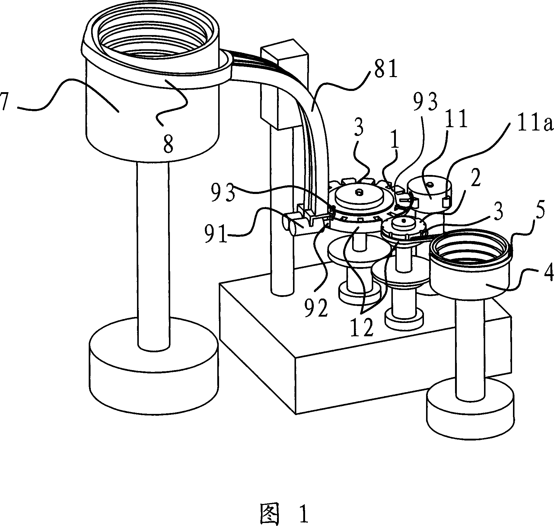
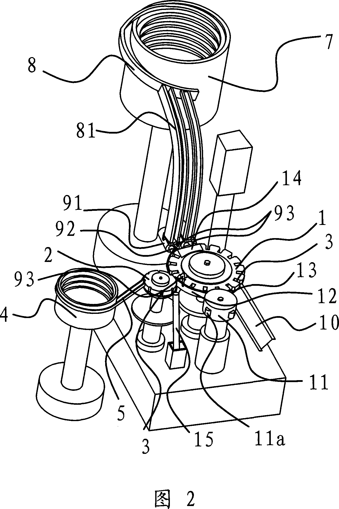
[0020] Embodiment 1: As shown in Figures 1 and 2, the automatic assembly machine for the infusion regulator is composed of a housing turntable 1, a roller turntable 2, a pressing roller 11, a housing feeding mechanism 9 and other components.

[0021] The edges of the housing turntable 1 and the roller turntable 2 are respectively provided with several evenly distributed notches 3, and the edges of the above two turntables are tangent. The roller feeder 4 is connected with a roller conveying guide rail 5 . The shell feeder 7 is connected with a shell conveying guide rail 8, and a shell feeding mechanism 9 is provided between the outlet of the shell conveying guide rail 8 and the shell turntable 1, and on the side of the shell turntable 1 A finished product discharge hopper 10 is provided. During work, the casing and the rollers are transported into the notches 3 of the casing turntable 1 and the roller turntable 2 respectively. Since the casing turntable 1 and the roller turn...

Embodiment 2

[0026]Embodiment 2: In this embodiment, two shell feeders 7 are provided on the side of the shell turntable 1, and each shell feeder 7 passes through a shell conveying guide rail with two conveying channels 81 8 is coupled with the housing turntable 1. The shell feeding mechanism 9 arranged between the discharge port of the shell conveying guide rail 8 and the shell turntable 1 includes a shell feeding cylinder 91, and the piston rod of each shell feeding cylinder 91 is fixedly connected with two The housing push rods 92 for pushing the housings into the corresponding notches 3 on the housing carousel 1 are provided one-to-one corresponding to the above-mentioned two conveying passages 81 . When a shell feeding cylinder 91 is working, it can control the work of two push rods 92 at the same time. The rest of this embodiment is similar to Embodiment 1, and will not be described in detail herein.


PUM


Abstract

The invention provides an automatic assembly machine of an infusion regulator, belonging to a mechanical technique field, which solves the problems of low assembling efficiency and low product quality of the existing kludge assembly, and comprises a shell rotary table and a roller rotary table; the edges of each rotary table are respectively provided with notches, and a roller feeder is connected with the shell rotary table by a wheel transportation guide rail; a shell feeder which is arranged on the lateral part of the shell rotary table is connected with the shell rotary table by a shell transportation guide rail, and a shell feed mechanism which is arranged between the discharge hole of the shell transportation guide rail and the shell rotary table comprises a shell feed cylinder which is connected with a shell pusher; a top pressure drum, the edge of which is tangent with the edge of the shell rotary table, is arranged on the lateral side of the shell rotary table, and a jacking block is arranged on the edge of the top pressure drum. The automatic assembly machine of the infusion regulator has the advantages of novel structure, automatic assembly, high assembling efficiency and excellent coordination between the shell and the roller.

Description

technical field [0001] The invention relates to the field of mechanical technology, in particular to an automatic assembly machine for an infusion regulator. Background technique [0002] The infusion regulator is composed of a housing and a roller. The roller is installed in the housing, and the infusion tube is pressed by the rolling of the roller to adjust the flow. In order to ensure that it is not polluted, the assembly of the infusion regulator should not be manually involved as much as possible. The biggest disadvantage of manual operation is that it is easy to attach germs, resulting in unqualified product hygiene requirements; at the same time, the assembly speed of manual operation is also low. [0003] For this reason, people have designed the device that can automatically assemble infusion regulator, and some have also applied for a patent. For example, the Chinese patent document discloses an assembly mechanism of a regulator assembly machine [CN200320108050.9]...

Claims


Application Information

Patent Timeline
Patent Type & Authority Applications(China)
IPC IPC(8): B23P21/00A61M5/14
Inventor 王兴章
Owner 王兴章
Learn More