Compensation circuit for implementing contravariant welding machine electric power outputting current steadily

A compensation circuit and power output technology, applied in the field of compensation circuit, can solve the problems of high cost, easy introduction of interference, complicated circuit and so on

Active Publication Date: 2008-08-06
AOTAI ELECTRIC
View PDF7 Cites 3 Cited by
  • Summary
  • Abstract
  • Description
  • Claims
  • Application Information

AI Technical Summary

Problems solved by technology

[0002] In the prior art, the control of the output constant current of the known inverter welding machine requires Hall element or s

Method used


Image

  • Compensation circuit for implementing contravariant welding machine electric power outputting current steadily
  • Compensation circuit for implementing contravariant welding machine electric power outputting current steadily

Examples


Embodiment Construction

[0017] The present invention will be further described below in conjunction with the drawings and embodiments.

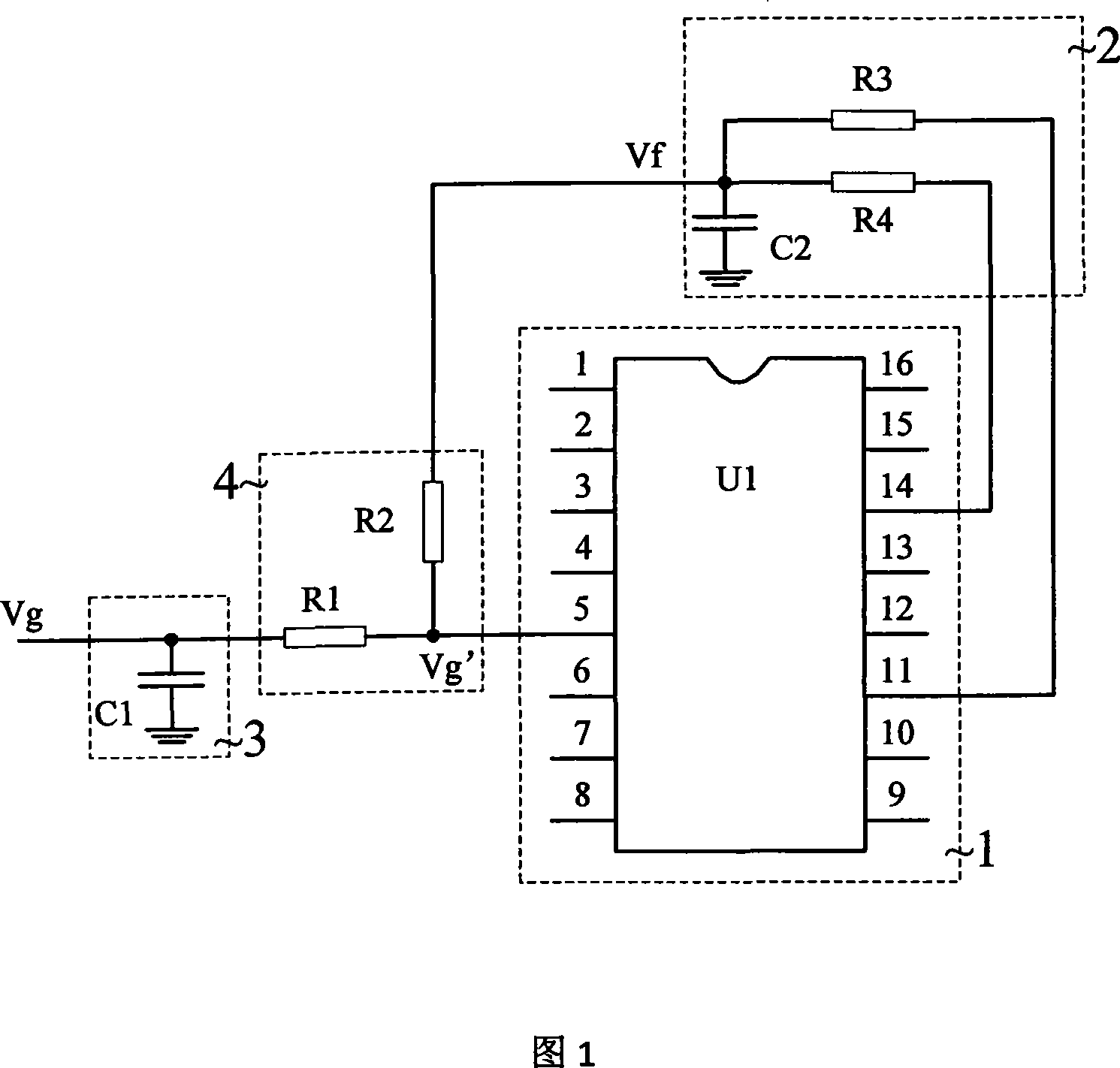
[0018] In Figure 1, it includes a pulse width modulator U 1 1. Pulse width modulator U 1 The pulse output terminal of 1 is connected to the driving pulse filter circuit 2, the driving pulse filter circuit 2 is connected to the compensation circuit 4, the compensation circuit 4 is connected to the current setting filter circuit 3, and the current setting filter circuit 3 is connected to the input current setting signal V g ; At the same time the compensation circuit 4 is also connected with the pulse width modulator U 1 1. The control end.

[0019] Pulse width modulator U 1 0Using current-type pulse width modulator.

[0020] Drive pulse filter circuit 2 uses resistor R 3 , R 4 And capacitance C 2 Composed of RC filter circuit.

[0021] Current given filter circuit 3 uses capacitor C 1 The capacitor filter circuit formed.

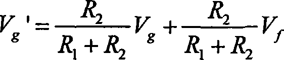
[0022] The compensation circuit 4 consists of tw...


PUM


Abstract

The invention discloses a compensating chain realizing a stable current output of a power supply of an inverter welder, which includes a pulse width modulator U1, wherein a pulse output terminal of the pulse width modulator U1 is connected with a drive pulse filter circuit; the drive pulse filter circuit is connected with the compensating chain; the compensating chain is connected with a current given filter circuit; the current given filter circuit is connected with an incoming current given signal Vg; meanwhile, the compensating chain is connected with a controlling end of the pulse width modulator U1. The compensating chain realizing a stable current output of a power supply of an inverter welder is characterized in that a Hall sensor or a shunt is saved; a controlling circuit is simplified; interruptions caused by a traditional sample circuit are eliminated; system responding time is accelerated; power supply output constant current characteristic is improved.

Description

Technical field [0001] The invention relates to a compensation circuit that realizes the stabilization of the output current of an inverter welding machine power supply. Background technique [0002] In the prior art, the known constant current output control of the inverter welding machine requires a Hall element or a shunt to sample and perform feedback and PI adjustment. The circuit is complicated, interference is easily introduced, and the cost is high. Summary of the invention [0003] The purpose of the present invention is to solve the shortcomings of the prior art and propose a compensation circuit that realizes the stable output current of the inverter welding machine power supply. This solution can eliminate the Hall sensor or shunt, simplify the control circuit, eliminate the interference introduced by the traditional sampling circuit, speed up the system response time, and improve the power output constant current characteristics. [0004] In order to achieve the abo...

Claims


Application Information

Patent Timeline
IPC IPC(8): B23K9/10B23K9/09
Inventor 张一鹏苗华伟刘晨李海涛汪伟
Owner AOTAI ELECTRIC
Why Eureka
Try Eureka