Eureka AIR delivers breakthrough ideas for toughest innovation challenges, trusted by R&D personnel around the world.

Bone marrow harvesting drill

A technology of bone marrow drill and bone marrow, which is applied in the direction of bone drill guidance, medical science, inoculation and ovulation diagnosis. The effect of cutting resistance

Inactive Publication Date: 2008-07-30
JIMRO CO LTD +1
View PDF1 Cites 17 Cited by
  • Summary
  • Abstract
  • Description
  • Claims
  • Application Information

AI Technical Summary

Problems solved by technology

The bone marrow needle greatly shortens the time to reach the bone medullary cavity, and the bone cutting chips excavated by the angled edge at the top end of the outer shell are discharged upward in the outer shell through the drill groove of the inner needle, so the bone cutting chips are not released into the body. It is excellent in that it is discharged into the jacket, but the viscosity of collagen contained in bone tissue hinders the discharge of excavation chips, and there is a limit to shortening the excavation time.

Method used


Image

  • Bone marrow harvesting drill
  • Bone marrow harvesting drill
  • Bone marrow harvesting drill

Examples


Embodiment Construction

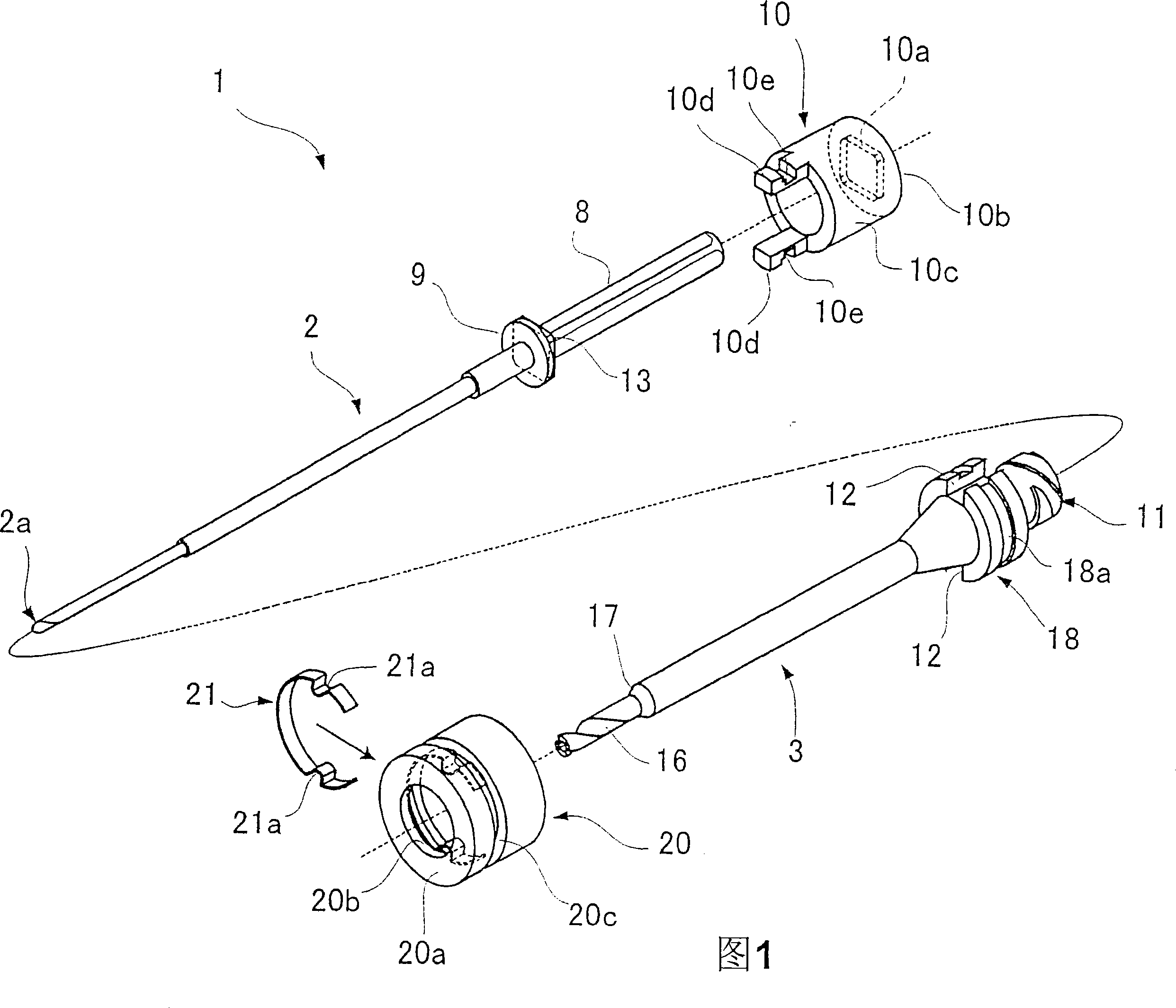
[0031] Hereinafter, preferred embodiments of the bone marrow drill according to the present invention will be described with reference to FIGS. 1 to 15 .

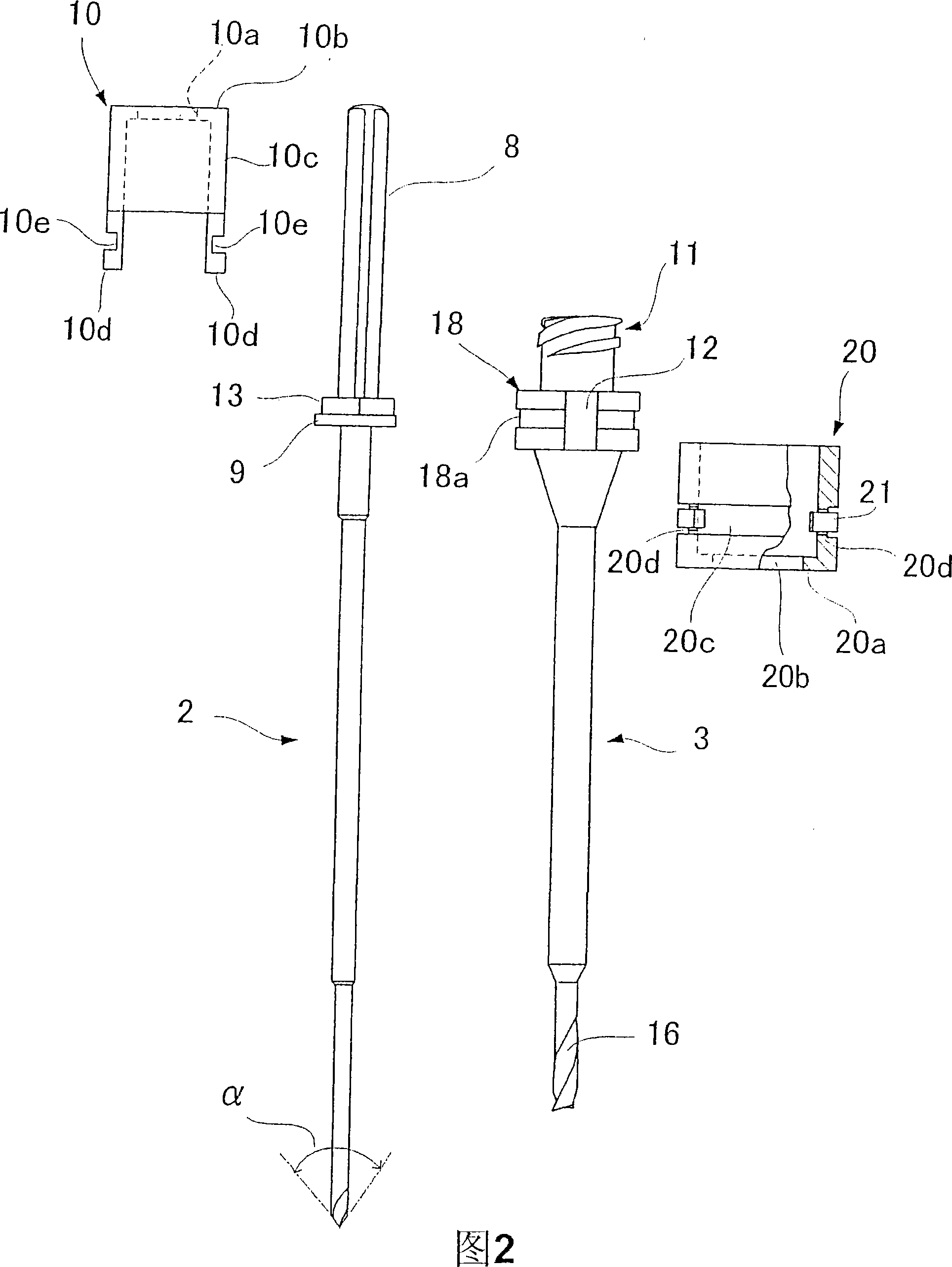
[0032] Fig. 1 is an exploded perspective view showing a first embodiment of a bone marrow drill. Figure 2 is an exploded plan view. As shown in FIG. 1 , the bone marrow drill 1 has an inner needle 2 and an outer sleeve 3 into which the inner needle 2 can be inserted.

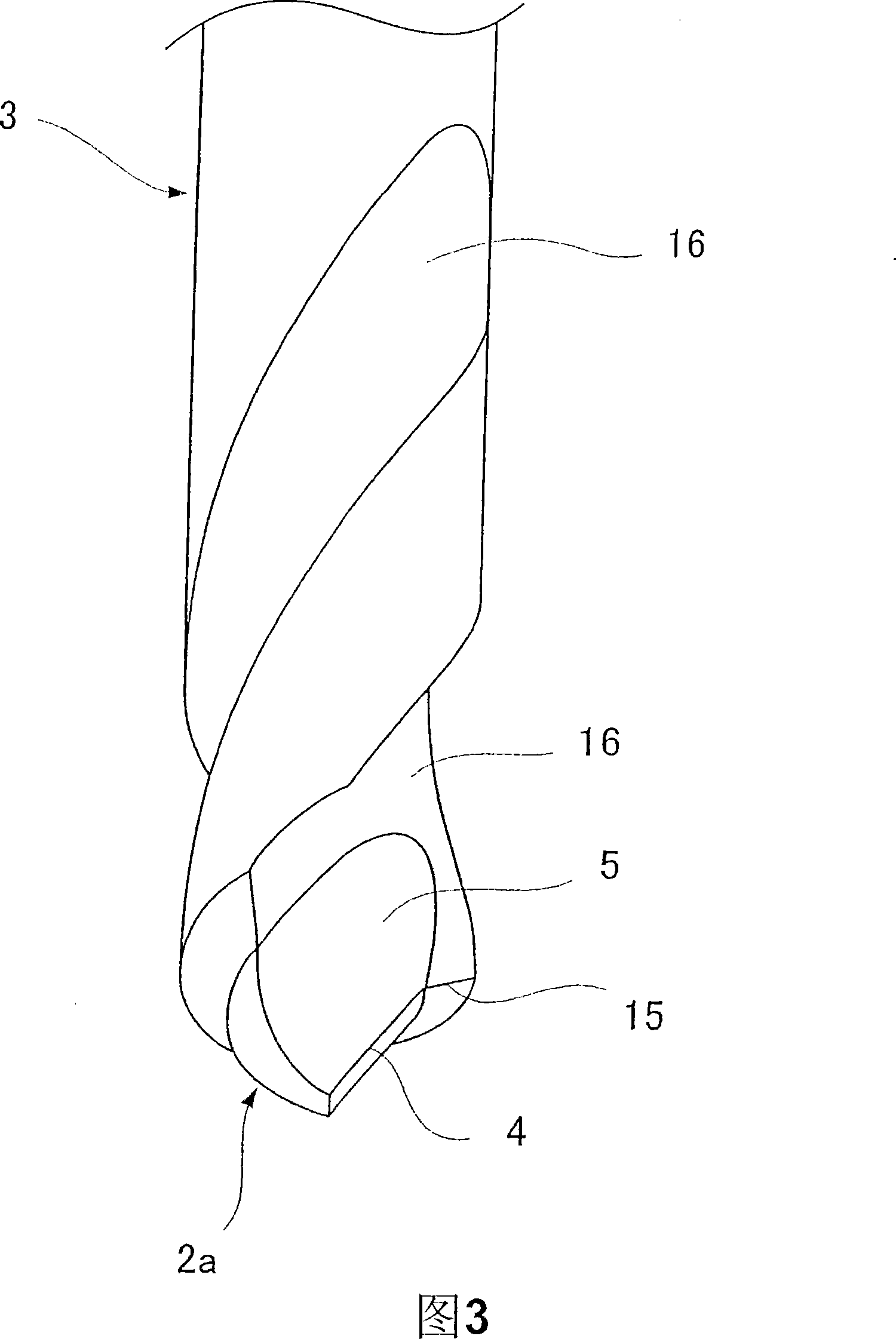
[0033] As shown enlarged in FIGS. 3 and 4 , the inner needle 2 has a cutting edge 4 and a groove 5 for discharging the cuttings cut by the cutting edge 4 at its tip. The cutting edge 4 is the line of intersection of the flank 6 and the rake face 7 . The tip portion 2a of the inner needle 2 preferably has a predetermined taper angle α (FIG. 2).

[0034] The rear of the inner needle 2 is formed with a shank 8 for gripping in a drill chuck. The inner needle 2 also has a circular flange 9 at the base of the shaft 8 . When the inner needle 2 is inserted into ...


PUM


Abstract

The bone marrow harvesting drill of the invention includes an inner needle having a cutting edge at the tip thereof; a tubular mantle that receives the inner needle thereinto so that the inner needle and the tubular mantle are detachably attached; and a lock mechanism that prevents the axial rotation of the tubular mantle and the inner needle relative to each other; the inner needle having a groove formed at the tip thereof projecting from the tubular mantle for discharging bone scraps produced by the cutting edge at the tip of the inner needle; and the tubular mantle having a cutting edge formed at the tip edge thereof and a helical groove extending from the tip edge to at least part of the peripheral surface of the tubular mantle so as to be flush with the groove of the inner needle.

Description

technical field [0001] The present invention relates to a bone marrow harvesting drill for excavating bone, harvesting bone marrow fluid and the like. Background technique [0002] Bone marrow fluid is generally collected by manually piercing the iliac bone with a bone marrow aspiration needle. This type of bone marrow puncture needle is formed by inserting an inner needle into a tubular sheath, and protruding the tip of the inner needle from the sheath. The bone marrow puncture needle with the handle attached to the jacket penetrates the skin and punctures the bone. After the needle tip reaches the bone marrow, only the inner needle is pulled out, and the jacket is left in the bone marrow cavity for use. [0003] As a method of collecting bone marrow fluid using this bone marrow puncture needle, the aspiration method can generally be used. The aspiration method is a method in which the casing of the bone marrow aspiration needle is connected to a syringe, and bone marrow ...

Claims


Application Information

Patent Timeline
Patent Type & Authority Applications(China)
IPC IPC(8): A61B17/16
CPCA61B10/025A61B17/1617A61B17/1633A61B17/1635A61B17/17A61B2010/0258A61B17/16
Inventor 池原进白藤泰司中村修二下田信夫佐渡克行
Owner JIMRO CO LTD
Why Eureka
Eureka Blog
Learn More