Control rod for a pressurized-water nuclear reactor

A nuclear reactor and control rod technology, applied in the field of control rods, can solve problems such as unsatisfactory reduction of casing expansion, and achieve the effect of improving performance

Inactive Publication Date: 2008-07-23
FRAMATOME GMBH
View PDF0 Cites 6 Cited by
  • Summary
  • Abstract
  • Description
  • Claims
  • Application Information

AI Technical Summary

Problems solved by technology

However, the expansion of the sleeve that accompanies the expansion of the absorption rod cannot be reduced satisfactorily by this measure.

Method used


Image

  • Control rod for a pressurized-water nuclear reactor
  • Control rod for a pressurized-water nuclear reactor
  • Control rod for a pressurized-water nuclear reactor

Examples


Embodiment Construction

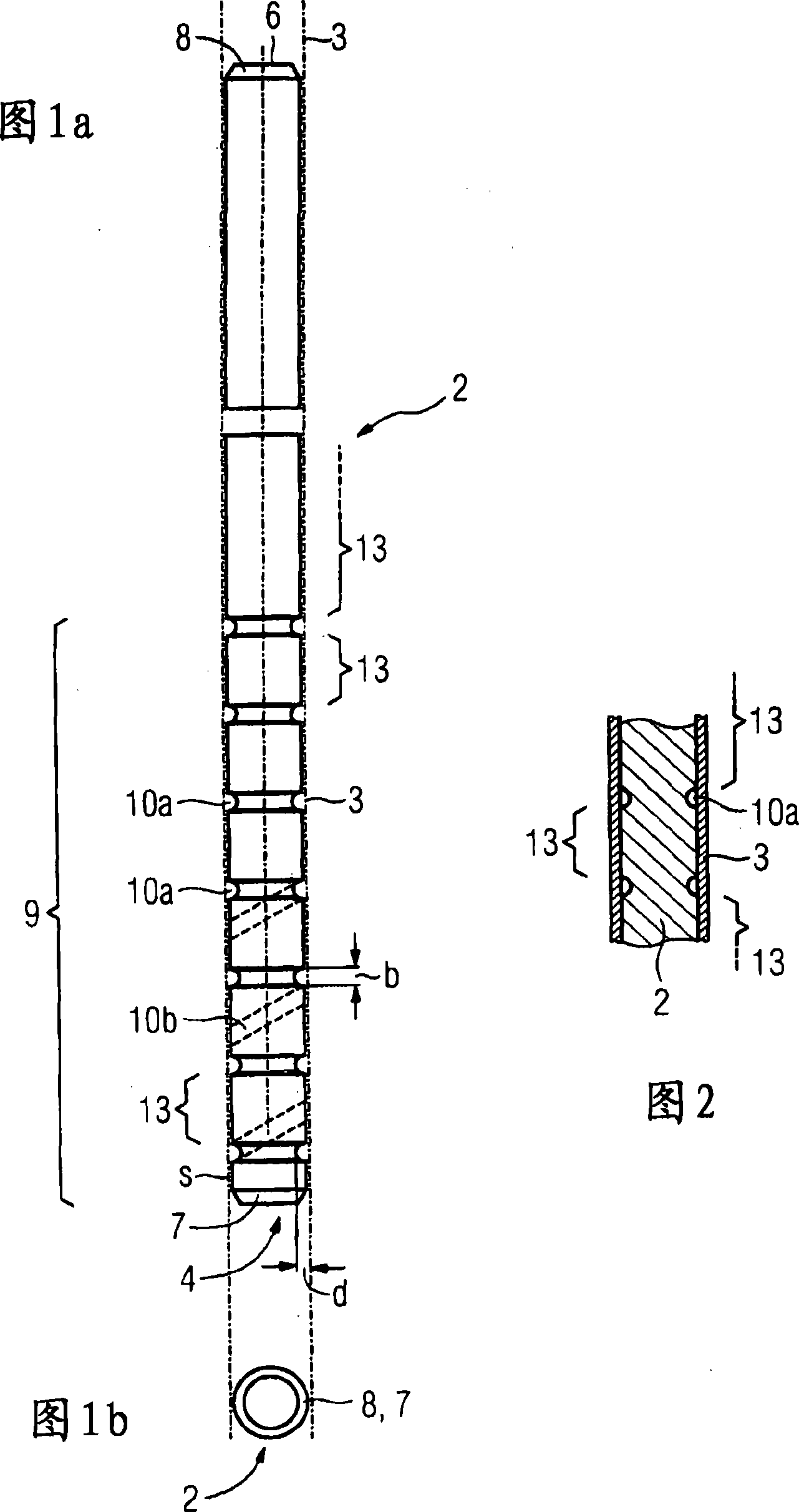
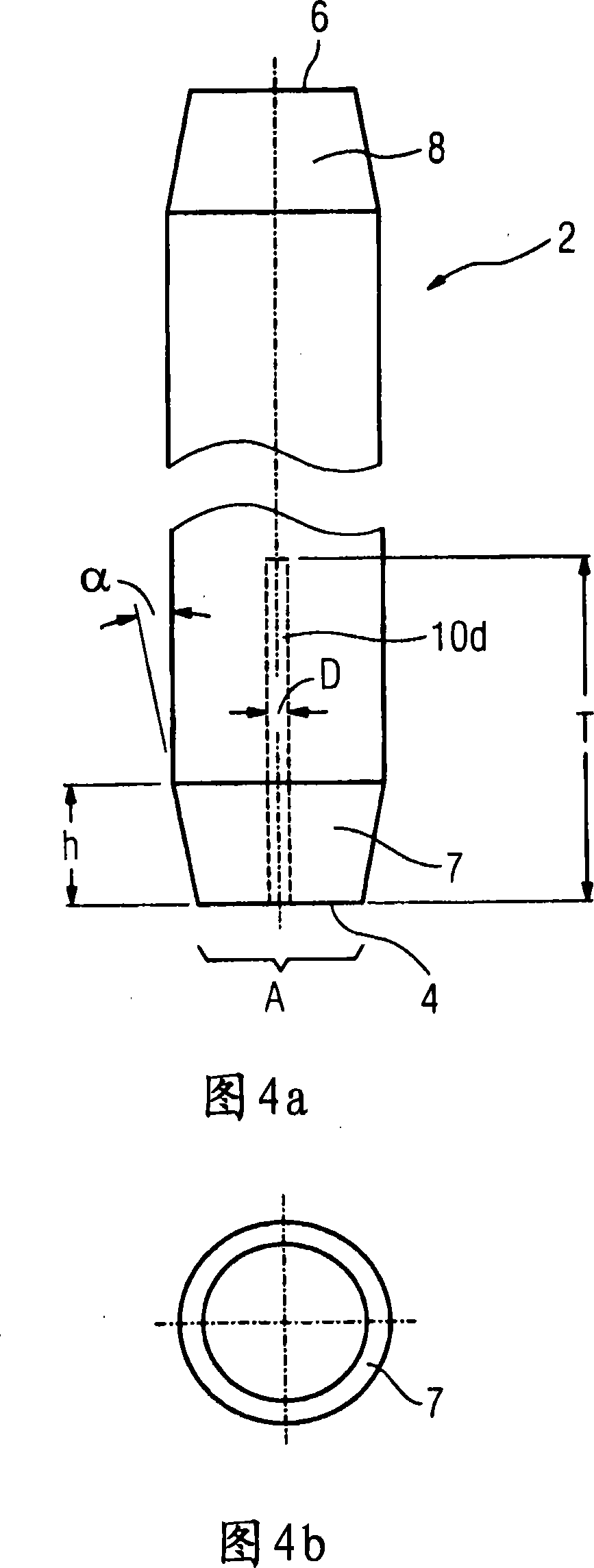
[0017] According to FIG. 1, an absorbent rod 2 has an essentially cylindrical shape. The absorption rod is conically shaped at its lower end 4 and upper end 6 , ie is provided with chamfers 7 or 8 . The absorption rod 2, which can be composed of a plurality of sub-rods in the axial direction, is accommodated in a sleeve 3, which is only indicated by dotted lines in the drawing, and which surrounds the absorption rod in a gas-tight manner. A “lower end” is to be understood here as the lower end of the absorber rod 2 through which the absorber rod is guided together with the sleeve 3 into the control rod guide tube of the fuel element in the installed state and during operation.

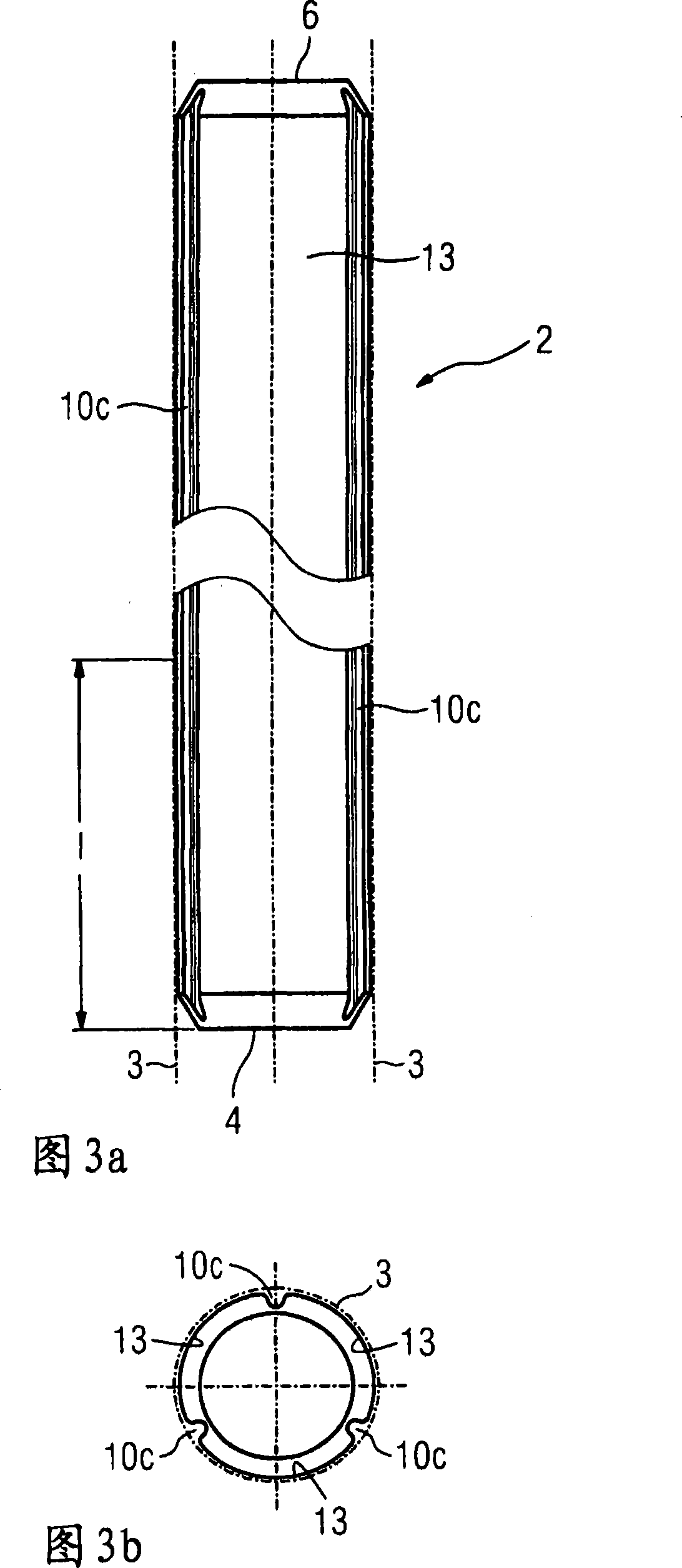
[0018] In the lower section 9 , which adjoins this conical region 7 , the absorber rod 2 is provided with a plurality of recesses in the form of annular grooves 10 a or grooves. In the region of these recesses, the absorber rod 2 thus has a cross-sectional area perpendicular to its longitudinal axis w...


PUM


Abstract

The present invention relates to a control rod for a pressurized-water nuclear reactor which comprises an absorber rod (2) which is arranged in a casing tube (3) and, at least in a lower section (9), is provided with at least one recess (10a-d), thus making free space be arranged when encircling the casing tube (3) of the absorber rod (2). This measure reduces the problems associated with an expansion in the volume of the absorber rod (2).

Description

technical field [0001] The invention relates to a control rod for a pressurized water nuclear reactor. Background technique [0002] The control rods of pressurized water nuclear reactors essentially consist of cylindrical casings, in which a cylindrical absorber rod is arranged. The sleeve is sealed outwardly and is filled with a gas, for example an inert gas, whose filling pressure is a maximum of 1.5 bar at room temperature. During operation, an increase in the volume of the absorber rods due to neutron absorption occurs in regions with a high neutron flux density, ie in particular in the lower region of the control rods. This increase in volume of the absorbing rod, known as swelling and increasing with operating time, can lead to a radial expansion of the sleeve in this region and, in the worst case, to its destruction, so the control rods in their calculations Replacement is necessary before the end of service life, that is, when the control rods themselves are still...

Claims


Application Information

Patent Timeline
Patent Type & Authority Applications(China)
IPC IPC(8): G21C7/10
CPCY02E30/30
Inventor 汉斯-彼得·富克斯弗洛里安·舍比茨彼得·德韦斯京特·菲舍尔阿尔方斯·罗佩尔特温弗里德·贝克
Owner FRAMATOME GMBH
Why Eureka
Try Eureka