Refrigerator
A technology for a refrigerator and a refrigerator, which is applied in the field of refrigerators and can solve the problems of increased manufacturing cost, reduced storage volume, and poor ease of use.
- Summary
- Abstract
- Description
- Claims
- Application Information
AI Technical Summary
Problems solved by technology
Method used
Image
Examples
Embodiment approach 1
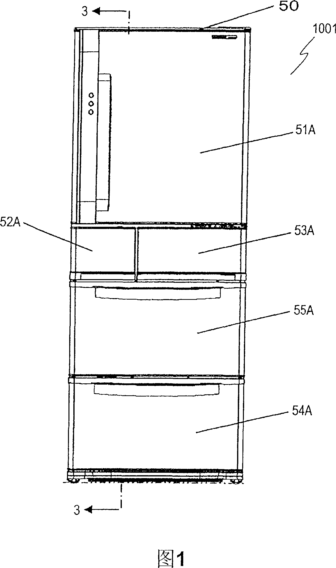
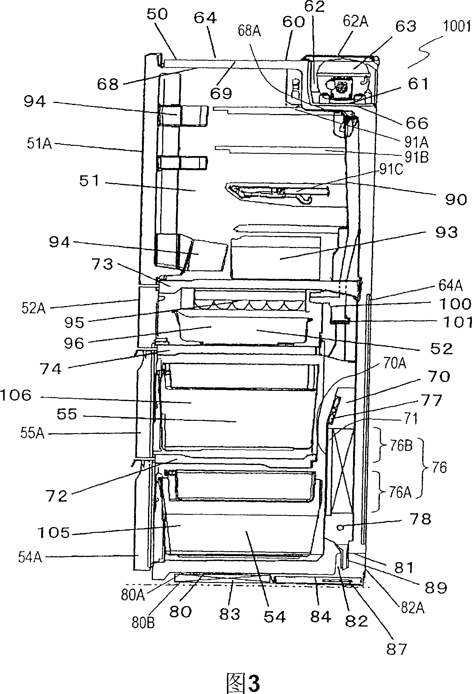
[0032] Fig. 1 is a front view of refrigerator 1001 according to Embodiment 1 of the present invention. FIG. 2 is a front view of heat insulating box 50 of refrigerator 1001 . Fig. 3 is a cross-sectional view along line 3-3 of refrigerator 1001 shown in Fig. 1 . 4 and 5 are perspective views of main parts of refrigerator 1001 .
[0033] The heat-insulating box 50 , which is insulated from the surroundings by a heat-insulating material such as rigid polyurethane foam, is divided into a plurality of zones to form a plurality of storage rooms. The uppermost storage room among the plurality of storage rooms is the refrigerator room 51 . Immediately below refrigerator compartment 51, ice maker compartment 52 and first freezer compartment 53 partitioned by a heat-insulating partition are arranged side by side. The lowermost store room is the second freezer room 54 . Between the ice making compartment 52 and the first freezing compartment 53 and the second freezing compartment 54 ...
Embodiment approach 2
[0090] Fig. 6 is a cross-sectional view showing refrigerator 2001 according to Embodiment 2 of the present invention. In FIG. 6 , the same reference numerals are assigned to the same parts as refrigerator 1001 according to Embodiment 1 shown in FIG. 1 , and description thereof will be omitted.
[0091] As shown in FIG. 6 , a second concave portion 203 is formed outside the cooling chamber 202 at the lower rear of the heat insulating box 201 . A condenser 204 is accommodated in the concave portion 203 . The other condensers of the condenser 204 can also be located in other positions.
[0092] Evaporator 205A for evaporating defrosting water includes evaporating pan 205 as a water storage unit and piping 87 . The evaporating dish 205 is installed at the bottom of the second concave portion 202 and is heated by heat transfer from the piping 87 that is a part of the condenser 204 . That is, the piping 87 functions as a heating unit that heats the defrosting water stored in the ...
Embodiment approach 3
[0096] Fig. 7 is a cross-sectional view of refrigerator 3001 according to Embodiment 3 of the present invention. In FIG. 6 , the same reference numerals are assigned to the same parts as refrigerator 1001 according to Embodiment 1 shown in FIG. 1 , and description thereof will be omitted.
[0097] As shown in FIG. 7 , a heat insulating box 301 made of a heat insulating material such as rigid polyurethane foam forms a plurality of storage rooms divided into a plurality of areas. Among these storage rooms, the uppermost and lowermost storage rooms function as refrigerating room 302 and freezing room 303 . A storage room located between refrigerator room 302 and freezer room 303 functions as vegetable room 304 . Refrigerator compartment 302 has revolving door 305 , and freezer compartment 303 and vegetable compartment 304 have drawer-type doors 306 and 307 .
[0098] The parts constituting the refrigeration cycle unit are arranged in the same manner as in the first embodiment. ...
PUM
 Abstract
Description
Claims
Application Information
 - R&D
- Intellectual Property
- Life Sciences
- Materials
- Tech Scout
- Unparalleled Data Quality
- Higher Quality Content
- 60% Fewer Hallucinations
Browse by: Latest US Patents, China's latest patents, Technical Efficacy Thesaurus, Application Domain, Technology Topic, Popular Technical Reports.
© 2025 PatSnap. All rights reserved.Legal|Privacy policy|Modern Slavery Act Transparency Statement|Sitemap|About US| Contact US: help@patsnap.com


