Vibration damping unit

A technology of sealing device and connecting device, applied in the direction of spring/shock absorber, vibration suppression adjustment, rotation vibration suppression, etc., can solve problems such as high price success

Inactive Publication Date: 2012-04-18
SCHAEFFLER TECH AG & CO KG
View PDF21 Cites 0 Cited by
  • Summary
  • Abstract
  • Description
  • Claims
  • Application Information

AI Technical Summary

Problems solved by technology

[0003] Such a torque transmission device configured as a dual mass flywheel has generally proven itself in motor vehicles of the middle class and above, especially in connection with diesel engines, but in smaller vehicles this device, despite its advantages, is due to Relatively high prices while still failing to succeed on a broad basis

Method used


Image

  • Vibration damping unit
  • Vibration damping unit
  • Vibration damping unit

Examples


Embodiment Construction

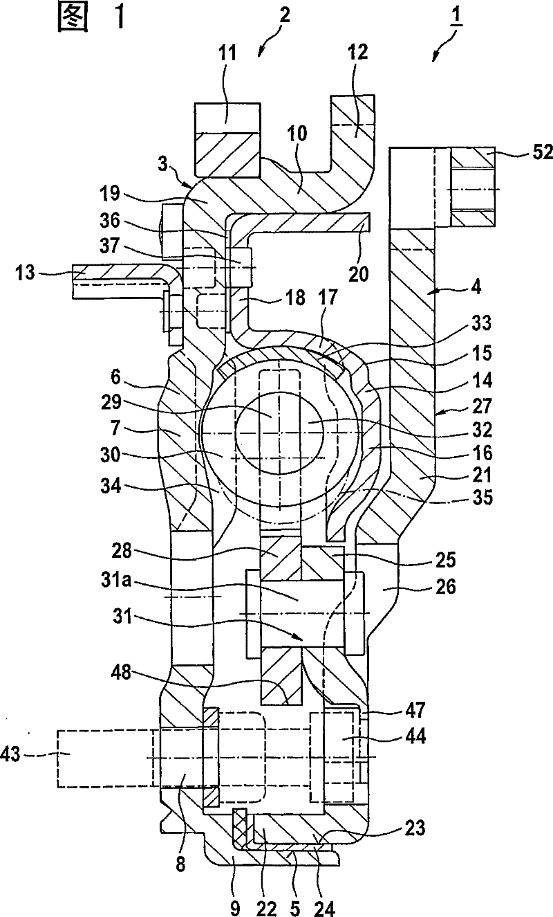
[0033] figure 1 The torsional vibration damping device 1 shown in the figure forms a so-called dual-mass flywheel 2, which comprises a primary mass 3 and a secondary mass 4, which are centered and rotatably mounted relative to each other via a bearing device 5 . In the exemplary embodiment shown, the bearing device 5 is formed by a so-called slide bearing. Reference is made to DE 198 34 728 A1 with regard to the function and possible configuration of such plain bearings, so that a detailed discussion of this is not necessary within the scope of the present application.

[0034] The primary mass 3 and the secondary mass 4 are formed by formed sheet metal parts, which are preferably configured as punched and / or pressed parts. Parts produced in this way can be produced practically without tools, whereby subsequent cutting operations can be dispensed with. If necessary, only the necessary screw threads have to be machined afterwards. However, this subsequent work process can b...


PUM


Abstract

The present invention relates to a dual-mass flywheel comprised of a primary mass which can be connected to the output shaft of an engine, and of a secondary mass which can be connected to the input shaft of a transmission, these masses being positioned concentric and axial to one another by means of at least one bearing and being able to rotate relative to one another in a limited manner againstthe action of a damping device with energy storage mechanisms. The energy storage mechanisms are accommodated in an annular ring-like chamber, which is formed by the components of the primary mass and which contains a viscous medium.

Description

technical field [0001] The invention relates to a device for damping vibrations, in particular between an engine and a drive train of a vehicle, which device forms a so-called dual-mass flywheel. In particular, the invention relates to a dual mass flywheel consisting of a primary mass connectable to the engine output shaft and a secondary mass connectable to the transmission input, the primary mass and the secondary mass Positioned concentrically and axially relative to each other by means of at least one bearing device and can be rotated relative to each other at least to a limited extent against the action of a damping device with an energy store, in particular a helical compression spring, wherein the energy The reservoir is received in an annular cavity, preferably formed by components of the primary mass and containing a viscous medium, and the components constituting the cavity and another mass carry or have some capacity for the energy The load area of ​​memory. Back...

Claims


Application Information

Patent Timeline
Patent Type & Authority Patents(China)
IPC IPC(8): F16F15/16F16F15/134F16F15/131
Inventor H・蒙德周斌R・基斯特纳
Owner SCHAEFFLER TECH AG & CO KG
Why Eureka
Try Eureka