
Ink-jet driving circuit with preheat function

A driving circuit and inkjet technology, applied in electrical components, electronic switches, printing, etc., can solve problems affecting printing quality, insufficient preheating temperature of inkjet head, etc.

Active Publication Date: 2008-07-16
MICROJET TECH
View PDF0 Cites 6 Cited by
  • Summary
  • Abstract
  • Description
  • Claims
  • Application Information

AI Technical Summary

Problems solved by technology

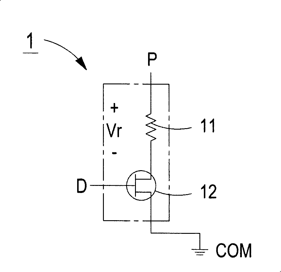
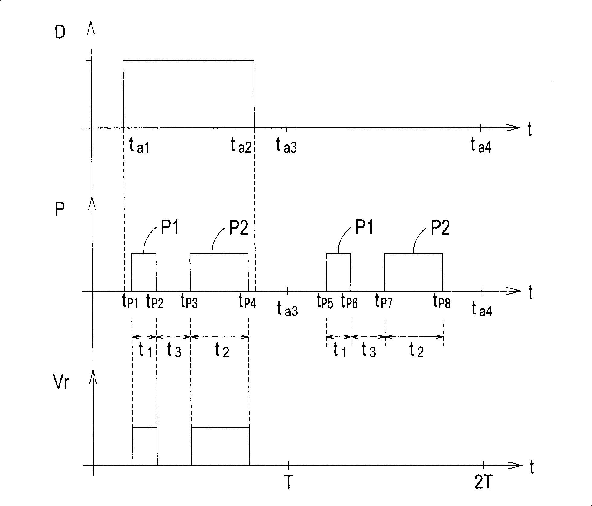
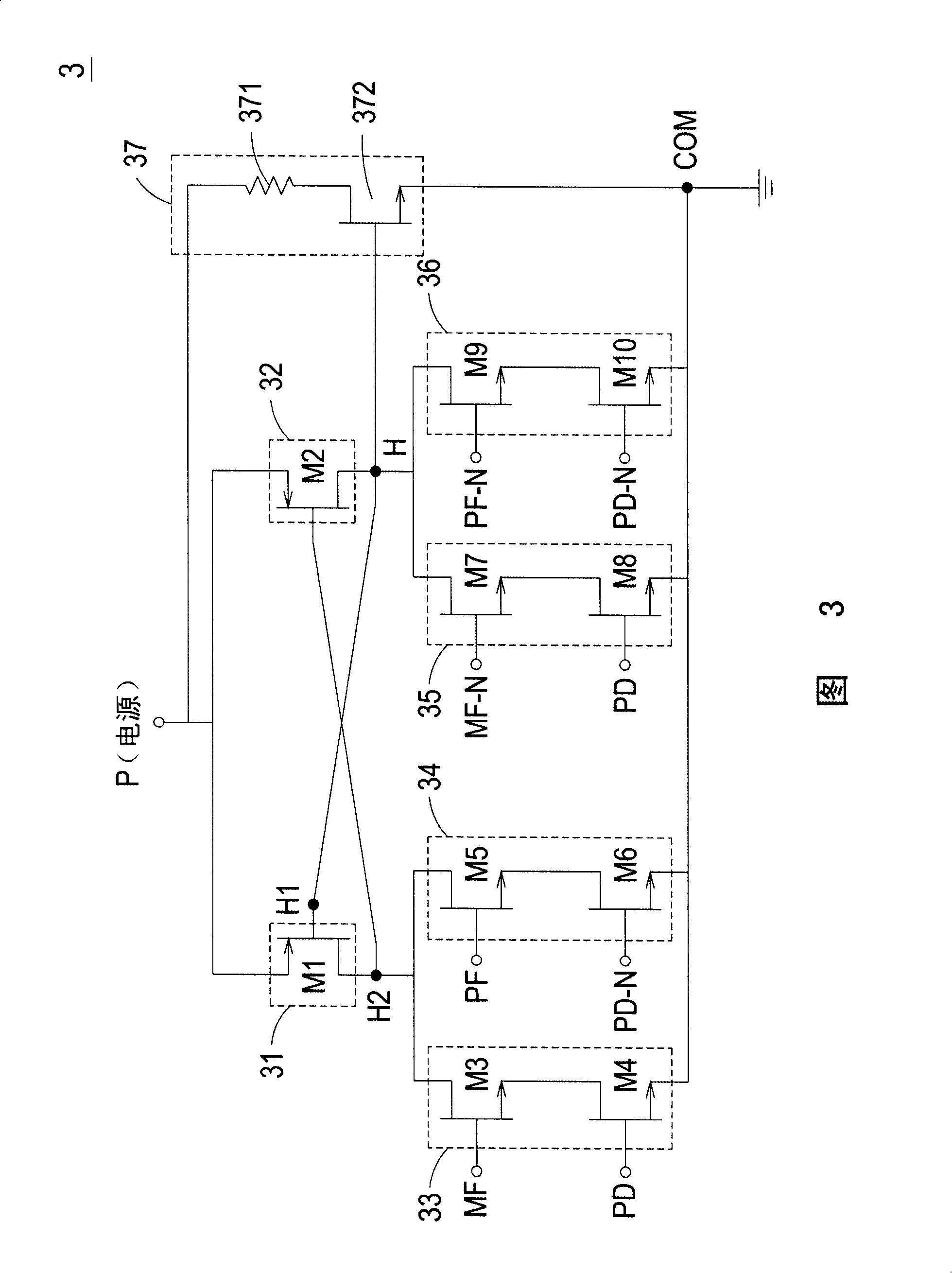
[0010] The main purpose of the present invention is to provide an inkjet drive circuit with preheating function, which is to make the heater heat part of the ink and generate air bubbles when the printing data signal and the heating control signal are high potential signals, and then push the ink out of the inkjet hole of the heating chip, on the contrary, when the printing data signal is a low potential signal and the preheating control signal is a high potential signal, the heater is controlled to preheat part of the ink and the inkjet head, The preheating temperature of the inkjet head is easy to control and the preheating efficiency is improved, so as to solve the problem that in the prior art, only the inkjet driving circuit that will perform column data printing will preheat part of the ink and the inkjet head, causing inkjet Insufficient preheating temperature of the head, which will affect the printing quality and other shortcomings

Method used


Image

  • Ink-jet driving circuit with preheat function
  • Ink-jet driving circuit with preheat function
  • Ink-jet driving circuit with preheat function

Examples


Embodiment Construction

[0028] Some typical embodiments embodying the features and advantages of the present invention will be described in detail in the description in the following paragraphs. It should be understood that the invention is capable of various changes in different aspects without departing from the scope of the invention, and that the description and illustrations therein are illustrative in nature and not limiting. this invention.

[0029] Generally speaking, the heating chip arranged inside the structure of the inkjet head has a plurality of inkjet holes arranged on the heating chip, and each inkjet hole has an inkjet drive circuit to control the inkjet Whether the hole is ink-jet or not, because the inkjet head has multiple ink-jet holes that need to be controlled, so there must be multiple inkjet drive circuits on the heating chip. The following will take a single inkjet drive circuit as an example to illustrate, but not This is the limit.

[0030] Please refer to FIG. 3 , which...


PUM


Abstract

The invention relates to an inkjet drive circuit with a preheating function. A heating chip arranged in an inkjet head structure comprises a heater and six switch circuits, which can receive power signals, printing data signals, heating control signals and preheating control signals. When the printing data signals and the heating control signals are high potential signals, part of the ink is heated by the heater to produce bubble so as to push the ink out of an inkjet hole of the heating chip; when the printing data signals are low potential signals and the preheating control signals are the high potential signals, part of ink and the inkjet hole are preheated by the heater to ensure that the preheating temperature of the inkjet head are easy to control and the preheating efficiency is enhanced.

Description

technical field [0001] The invention relates to an inkjet driving circuit, especially an inkjet driving circuit suitable for a heating chip of an inkjet head and having a preheating function. Background technique [0002] In recent years, with the popularization of personal computers and the rapid development of the Internet, inkjet printers have become very common auxiliary equipment, widely used in homes, personal studios, and even in various industries. The main advantages of inkjet printers are low price, low noise during operation, and excellent printing quality, and they can be printed on various media, such as general paper, special inkjet printing paper, photo paper, and special transparencies. [0003] As we all know, there are many factors that affect the printing quality of inkjet printers, such as the composition of ink, the choice of paper, and the ink supply method of ink cartridges, etc. However, ink cartridges are an indispensable component for any inkjet pri...

Claims


Application Information

Patent Timeline
IPC IPC(8): B41J2/05B41J2/14H03K17/687
Inventor 欧享沛
Owner MICROJET TECH
Learn More