
Electrically Large complex target and rugged face background composite electromagnetic scattering numerical value emulation method

A composite electromagnetic and numerical simulation technology, applied in the direction of electromagnetic wave re-radiation, utilization of re-radiation, image data processing, etc. Higher-order scattering terms, etc.

Inactive Publication Date: 2008-07-09
FUDAN UNIV
View PDF0 Cites 39 Cited by
  • Summary
  • Abstract
  • Description
  • Claims
  • Application Information

AI Technical Summary

Problems solved by technology

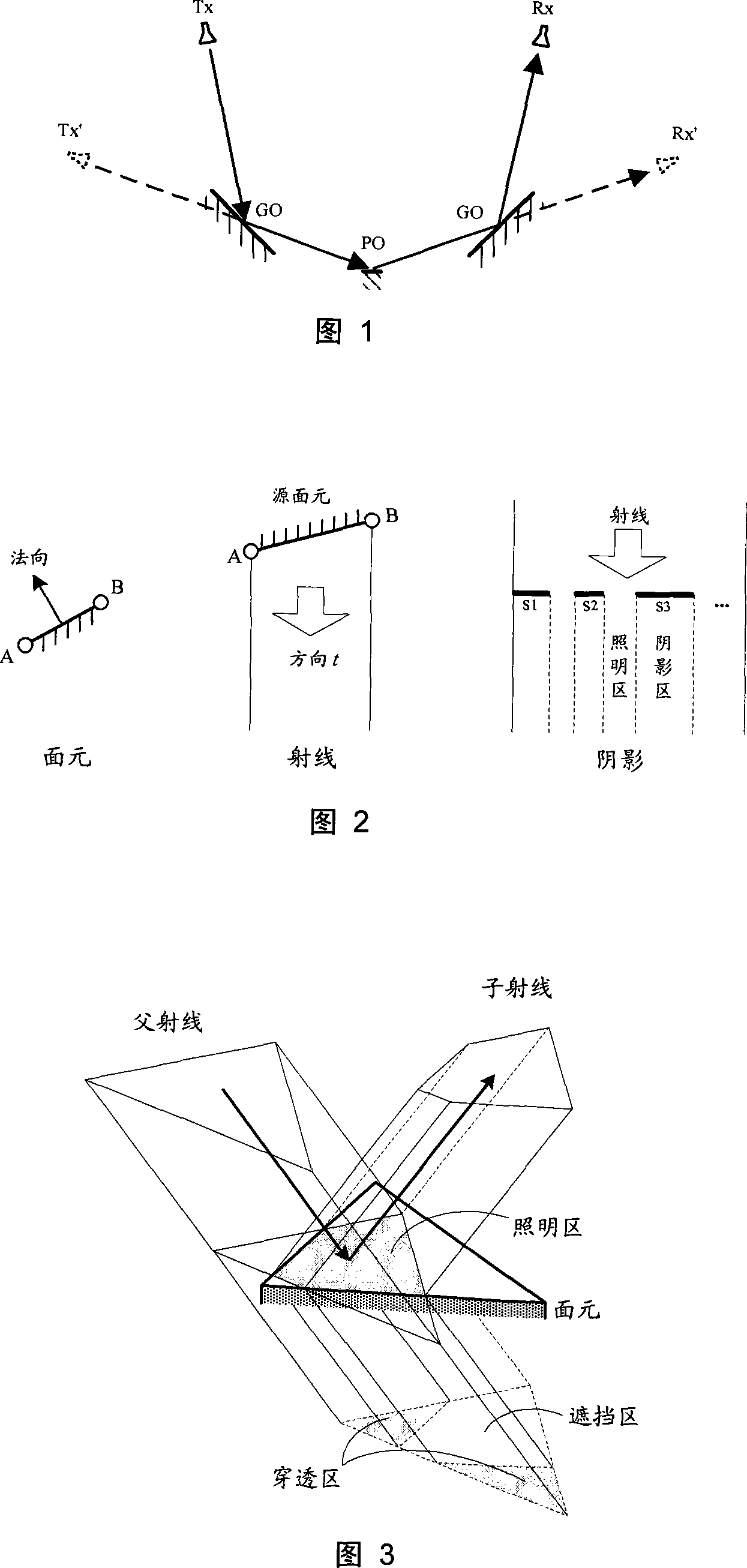
In addition, Rius et al. [5] developed a tool for real-time calculation of the target RCS using a graphics hardware accelerator. This tool uses the functions of the existing optical image processing kernel to quickly calculate the shading and scattering of the surface element, although only one scattering and diffraction field, but because of its fast calculation speed, it is mostly used
[0004] Among the existing methods, most methods cannot calculate the third-order and above higher-order scattering. Although the SBR method adopted by XPatch software can calculate higher-order scattering, the last scattering must be PO scattering and the rest are GO reflections. This fails to take into account many other possible higher order scattering terms
There is still a lack of reliable and practical research on the composite RCS simulation under the condition of the coexistence of volume targets and area targets

Method used


Image

  • Electrically Large complex target and rugged face background composite electromagnetic scattering numerical value emulation method
  • Electrically Large complex target and rugged face background composite electromagnetic scattering numerical value emulation method
  • Electrically Large complex target and rugged face background composite electromagnetic scattering numerical value emulation method

Examples


Embodiment Construction

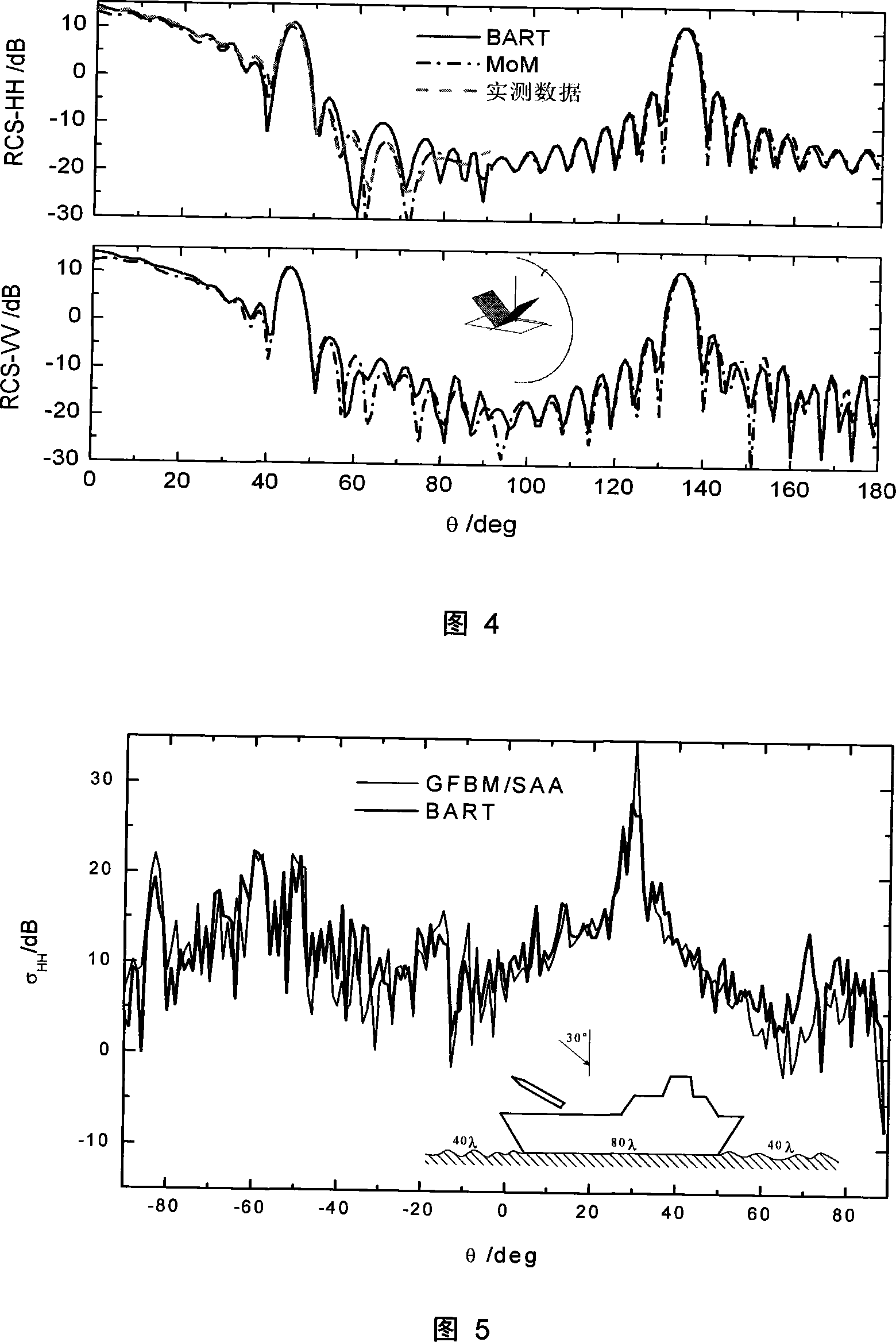
[0077] First take the dihedral angle as an example to calculate the target RCS. The two faces of the dihedral angle are the same size, the length and width are 5.6088λ (λ is the wavelength), the included angle is 90°, and the observation frequency is 9.4GHz. Calculate the backscattering of this dihedral angle with the BART method of the present invention:

[0078] First establish the geometric model of the dihedral angle, and divide its surface into seamlessly connected polygonal plane elements. Here, it can be directly divided into two rectangular plane elements, and the connection is an edge;

[0079] Change the incident angle from 0° to 180°. For each incident angle, perform 3-order ray tracing from the forward direction of the incident and the reverse direction (backward direction) of the scattering, and record the ray illumination area on each surface element and edge along the way and shaded areas;

[0080] Calculate and accumulate the scattering items produced by the t...


PUM


Abstract

The invention belongs to the technical field of radar target monitor, in particular to a numerical simulation method of composite electromagnetic scattering of electric-large complex body target and coarse land-sea surface background. The method comprises the following steps of : respectively dividing a body target and a surface target into polygonal planar elements; respectively tracing the front incident direction and the inverse scattering direction with rays and recording rays of each order irradiating the scattering elements; constructing the tracing path by an arbitrary pair of front and back rays meeting at the same planar element or edge to form a scattering item by adopting the resolution of body target scattering element, or the edge physic-optics scattering or physical diffracting as well as the coarse surface element scattering and through the surface-body target scattering and interaction described by scattering ray tracing; and accumulating the scattering items of all planar elements to obtain the composite electromagnetic scattering of the body target and the surface target. The method can numerically simulate composite electromagnetic scattering or radar scattering cross section of a coarse land-sea surface background with complex shape, electric-large size and a three-dimensional body target at high speed and high efficiency.

Description

field of invention [0001] The invention belongs to the technical field of radar target monitoring, and in particular relates to a numerical simulation method of compound scattering and radar scattering cross section under the coexistence condition of complex three-dimensional body target and rough sea surface background. Background technique [0002] The complex electromagnetic scattering modeling of electrically large complex objects and the ground-sea background and the calculation of radar cross section (RCS, RadarCross Section) are a difficult problem in radar target monitoring and signal interpretation. Due to the complexity limitation of precise numerical methods in electrically large-scale problems, the high-frequency approximation method becomes a fast and effective method to solve such problems. Although the high-frequency method is an approximate calculation, it is often sufficient to give a high degree of accuracy in the solution of the problem, while having a goo...

Claims


Application Information

Patent Timeline
Patent Type & Authority Applications(China)
IPC IPC(8): G01S7/48G01S17/66G06T17/30
Inventor 金亚秋徐丰
Owner FUDAN UNIV
Learn More