
Comprehensive test platform

A technology of comprehensive test bench and test bench, which is applied in the field of comprehensive test bench, can solve the problems of low work efficiency, waste of lubricating oil, messy assembly workshop, etc., and achieve the effects of convenient adjustment, accurate testing and convenient production

Inactive Publication Date: 2008-07-09
RG PETRO MACHINERY GROUP
View PDF0 Cites 9 Cited by
  • Summary
  • Abstract
  • Description
  • Claims
  • Application Information

AI Technical Summary

Problems solved by technology

In the known technology, when carrying out the running-in test of the box parts such as the turntable, the chain box and various gearboxes, the parts to be run-in are directly fixed on the ground, and the running-in is directly driven by the motor. Since there is no reference table as the basis, The accuracy of the test is not high; when filling and releasing lubricating oil, because there is no fixed filling and draining device, the work efficiency is low, the lubricating oil is wasted, and the ground is polluted
The static balance test of pulleys and shaft parts is carried out on the static balance test bench, which is fixed at a certain position alone, which is only suitable for testing some parts and has poor versatility
At the same time, the above-mentioned test devices are placed everywhere in the assembly workshop. No matter how they are placed, they will affect the overall appearance of the assembly workshop, making the assembly workshop look messy and disorderly, like a small workshop, which does not meet the production management of modern enterprises standard

Method used


Image

  • Comprehensive test platform
  • Comprehensive test platform
  • Comprehensive test platform

Examples


Embodiment Construction

[0015] The present invention will be further described below in conjunction with the accompanying drawings.

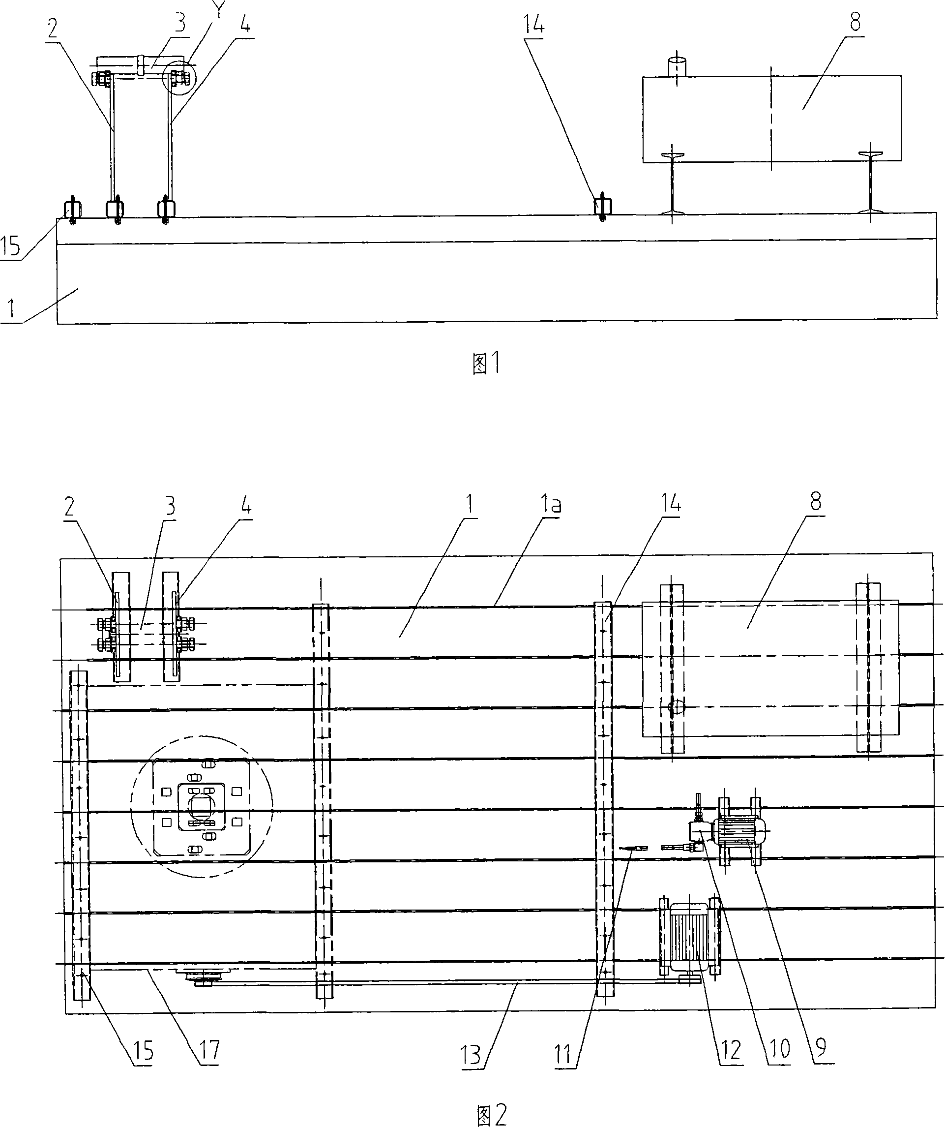
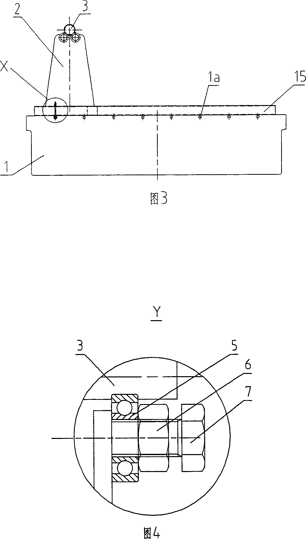
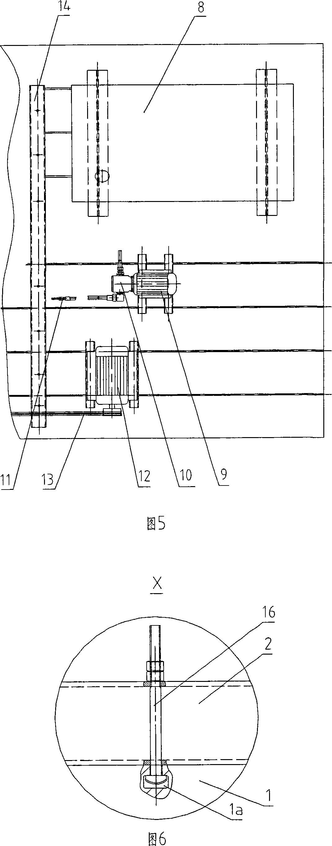
[0016] As shown in Fig. 1, Fig. 2 and Fig. 3, the comprehensive test bench of the present invention includes a platform 1, a static balance test device, a run-in test device, and a refueling and oil pumping device on which the upper plane is a reference plane, and the upper plane of the platform 1 is provided with certain intervals Transverse T-slot 1a.

[0017] As shown in Figure 1, Figure 2, Figure 3, Figure 4, and Figure 6, the static balance test device consists of a mandrel support 2, a mandrel 3, a mandrel support 4 and a pair of bearings 5 ​​connected to each mandrel support , the mandrel support 2 and the mandrel support 4 are fixed on the platform 1 through the T-bolt 16 and the T-slot 1a of the platform 1, between a pair of bearings 5 ​​of the mandrel support 2 and a pair of bearings 5 ​​of the mandrel support 4 The bearings 5 ​​are connected to the mandrel ...


PUM


Abstract

The invention relates to a comprehensive test platform for running attrition test of box components and for static balance test of wheel and shaft parts. The comprehensive test platform comprises a platform with an upper reference plane, a static balance test device, a running attrition test device, an oil adding and pumping device and T-shaped grooves provided arranged on the platform at intervals. The static balance test device is composed of two core shaft supports, core shafts, a pair of rollers connected with each core shaft support, wherein the core shafts are arranged on two pairs of rollers on both ends. The running attrition test device includes a power device, a transmission mechanism and two press plates, wherein, the power device is connected with the transmission mechanism, and the transmission mechanism is connected with an input shaft of a box body to be tested. The oil adding and pumping device comprises an oil tank, a motor and a gear pump, wherein, the suction inlet of the gear pump is connected with the pipe line of the oil tank; the exit hole of the gear pump is connected with a hose joint and an oil nozzle. All fixed elements on the platform are connected with the platform through T-shaped screws. The invention has the advantages of accurate testing, good generality, good practicality, simple structure, convenient fabrication and low cost.

Description

technical field [0001] The invention relates to a comprehensive test bench for running-in tests on box parts and static balance tests on wheel and shaft parts in the machinery manufacturing industry. Background technique [0002] The transmission components used in petroleum machinery such as drilling rigs and workover rigs, such as turntables, chain boxes and various gearboxes, must be subjected to no-load running-in tests before the complete assembly of drilling rigs and workover rigs, mainly to test gears and sprockets For meshing with the chain and loading conditions, lubricating oil should be filled in the box before the running-in test, and the remaining lubricating oil should be released after the running-in test; shaft and wheel parts such as various transmission shafts and pulleys should be checked before assembly Do static balance test, these works are carried out in the assembly workshop. In the known technology, when carrying out the running-in test of the box p...

Claims


Application Information

Patent Timeline
IPC IPC(8): G01M13/02G01M1/12G01M13/04F16N13/22
Inventor 李文艺张勇胜庆田周广智刘俭余利军王文尔吴文晓华斌李全德杨延娟
Owner RG PETRO MACHINERY GROUP
Learn More