Eureka AIR delivers breakthrough ideas for toughest innovation challenges, trusted by R&D personnel around the world.

Semi-directional regulating circuit

A regulating circuit, semi-directional technology, applied in the conversion equipment with intermediate conversion to AC, irreversible AC power input conversion to DC power output, etc., can solve the problem that the accuracy of output voltage regulation exceeds the standard, cannot be compensated on demand, output To avoid problems such as limited circuit compensation, to achieve the effects of improved reliability, favorable power supply efficiency, and large voltage regulation amplitude

Active Publication Date: 2011-05-18
VERTIV CORP
View PDF0 Cites 0 Cited by
  • Summary
  • Abstract
  • Description
  • Claims
  • Application Information

AI Technical Summary

Problems solved by technology

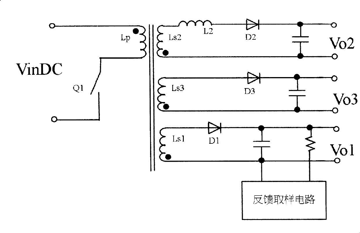
[0005] 1. When a certain output adopts this inductive voltage regulation technology, the reduced energy is compensated to other outputs, including other output channels that have high output but voltage regulation accuracy does not exceed the standard, which may cause these output The output voltage regulation accuracy of the circuit thus exceeds the standard;
[0006] 2. When a certain output adopts this inductive voltage regulation technology, the reduced energy is compensated to other outputs, including the main output with feedback. When the main output voltage is affected to a certain extent, it will inevitably cause duty Therefore, this voltage regulation technology has limited compensation for the output circuit with low output;
[0007] 3. When a certain output channel adopts this inductive voltage regulation technology, the compensation obtained by other output channels is related to the transformer, which is basically fixed and cannot be compensated on demand.

Method used


Image

  • Semi-directional regulating circuit
  • Semi-directional regulating circuit
  • Semi-directional regulating circuit

Examples


no. 1 example

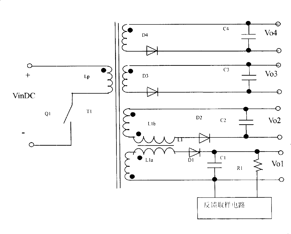
[0022] refer to figure 2 The first embodiment of the present invention is shown. This embodiment is to adjust a four-way output flyback multi-way power supply. The signal source has an auxiliary circuit whose output voltage is higher than its rated value.

[0023] Such as figure 2 As shown, the voltage of the output auxiliary circuit Vo2 is relatively high, and the voltage of the output auxiliary circuits Vo3 and Vo4 is relatively low. Now we add one or two winding transformers before rectification and filtering between Vo2 and the output main circuit Vo1 with main feedback, and the two windings are respectively connected in series. In the two output circuits, the currents of the two windings flow in from the terminals with the same name of the transformer. The winding of transformer L1 connected in series with Vo1 is assumed to be L1a, the number of turns is Na, the voltage on L1a is VL1a; the winding of transformer L1 connected in series with Vo2 is assumed to be L1b, the...


PUM


Abstract

The invention provides a semi-directional adjusting circuit, which is used for adjusting output signals of at least an auxiliary circuit of a signal source. The semi-directional adjusting circuit includes a transformer having at least two windings. An output main circuit of the signal source is in series with a first winding of the transformer; the auxiliary circuit requiring signal adjustment is in series with at least the other winding of the transformer. By adopting the technique of the semi-directional adjusting circuit provided by the invention, the voltage adjusting amplitude can be large without loss increase, and thus the invention is beneficial for increasing power efficiency and also the reliability. The semi-directional energy consumption can be controlled through the duty cycle of main circuit adjustment, which is free from the limit by a relatively high quantity or a relatively low quantity of specific output of the auxiliary circuit. The invention can realize complete compensation under the condition that the output of all the auxiliary circuits is relatively low. The voltage adjusting amplitude can be directly used for quantum calculation, without effect from the duty cycle. Besides, the voltage adjusting cost is low, the performance cost ratio is high, and the electromagnetic characteristics of relevant output circuits can be improved as well.

Description

technical field [0001] The invention relates to the technical field of basic electronic circuits, in particular to a semi-directional regulating circuit. Background technique [0002] At present, in the multi-output power supplies used in the industry, due to the existence of transformer turns that can only be integer turns and other factors, especially the number of transformer turns is rounded (for a few special-application transformers, it may be possible to take half turns, but the number of half turns The transformer has special requirements for the air gap mode of the magnetic core, the distribution of the winding, or the way of the winding lead-out wire, which will increase the winding cost of the transformer), and the specific turns of each output winding of the transformer are generally rounded up, and The rounding and rounding of each winding may be inconsistent, and the rounded voltage turns ratio of each auxiliary winding may also be inconsistent with the rounded...

Claims


Application Information

Patent Timeline
Patent Type & Authority Patents(China)
IPC IPC(8): H02M3/28H02M7/06
Inventor 吴连日
Owner VERTIV CORP
Why Eureka
Eureka Blog
Learn More