Multi-purpose signal system for pedestrian and traffic control

A traffic signal and signal technology, applied in the field of campus, can solve the problems of traffic flow interruption, traffic accidents, and the inability to display the remaining time, etc., and achieve the effect of reducing installation and maintenance costs and reducing construction

Inactive Publication Date: 2008-06-04
金钟海 +2
View PDF2 Cites 7 Cited by
  • Summary
  • Abstract
  • Description
  • Claims
  • Application Information

AI Technical Summary

Problems solved by technology

[0008] In order to overcome the above problems, a single pedestrian traffic signal system was introduced. However, the single system uses two digits to display the remaining time, which causes difficulties for the handicapped and illiterate with low vision. It is also difficult to recognize from a considerable distance.
[0009] Also, conventional audible signal generators for blind people at intersections are designed to generate only electronic sound signals, so blind people cannot discern the remaining time for the change of the walking signal, which causes inconvenience to blind pedestrians
[0010] Moreover, the traditional pedestrian traffic signal system cannot diagnose system faults by itself, nor can it remotely warn the management equipment of faults, which will cause faults to be ignored for a long time
[0011] Also, conventional pedestrian traffic signal systems cannot detect the presence or absence of pedestrians at intersections of two-way streets, and it can cause unnecessary interruptions in traffic flow since the signal changes even when there are no pedestrians
[0012] Moreover, traditional pedestrian traffic signal control systems in school districts rely on manual signals from security guards, which makes it difficult to simultaneously control vehicles and pedestrians to keep children safe
[0013] Moreover, for the driver, the traditional traffic signal system cannot display the remaining time of each signal change at the intersection, because the driver cannot predict the time when the signal is about to change and rushes through, which will cause traffic accidents

Method used


Image

  • Multi-purpose signal system for pedestrian and traffic control
  • Multi-purpose signal system for pedestrian and traffic control
  • Multi-purpose signal system for pedestrian and traffic control

Examples


Embodiment Construction

[0034] Referring to the accompanying drawings, the following is a detailed description of the system structure and operation of the present invention.

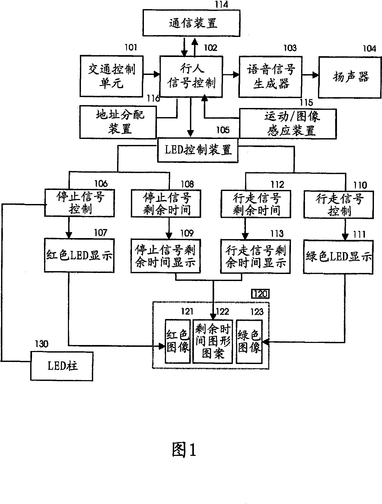
[0035] Fig. 1 is a detailed schematic block diagram of the present invention, and Figs. 4, 5, 6 and 7 illustrate examples of signal lamp caps according to the present invention. As described on Fig. 1 and Fig. 4, the present invention comprises control device (102), and it is used for receiving the signal control data from traffic control unit (101), and is used for each stop signal or walking signal by calculating The remaining time of the signal change is used to control the function of the system, and the time interval of the signal change is divided by the number of graphic patterns, so as to transmit the data to the LED control device of the system for display. The LED signal lamp head (120) includes a multi-color LED panel and Housing to display the stop signal represented by the red graphic image, the go signal represen...


PUM


Abstract

The present invention relates to a pedestrian signaling system for not only ordinary pedestrians but also blind, weak-sighted disabled and illiterate by displaying the remaining time of each signal change with an image pattern at a signal lamp head and generating a voice signal in real time. Reduced system construction, system installation and maintenance by combining five pedestrian signal functions such as go signal, stop signal, remaining time for each red / green signal and / or voice generator for the blind in one signal light head cost of. At the same time, by installing LED posts on stop lines at intersections to automatically flash the LED posts to warn drivers when the go signal is in ON mode, the present invention provides an effective double safety traffic signal system, especially for school zones.

Description

[0001] Cross References to Applications [0002] This application is a partial continuation of Korean Patent No. 0329419 (Application No. 1999-0027862), Korean Patent No. 0572343 (Application No. 2003-0061271) and Korean Utility Model Patent No. 028229 (Application No. 2002-0018926) , and presented at the same time. technical field [0003] The present invention relates to a pedestrian signaling system for not only ordinary pedestrians but also blind, partially sighted disabled and illiterate by displaying the remaining time of each signal change in an image pattern at a signal head and generating a voice signal in real time. [0004] Therefore, the present invention provides a technique to reduce the cost of system construction, installation and maintenance by combining five signals such as the walking signal, the stop signal, the remaining time of each red and green signal, and the sound signal for the blind. Pedestrian signaling functions are combined in a single signal he...

Claims


Application Information

Patent Timeline
Patent Type & Authority Applications(China)
IPC IPC(8): G08G1/096G08G1/095
CPCG08G1/095G08G1/096G08B3/10G08G1/075
Inventor 金钟海汤米·Y·金韩庆子
Owner 金钟海
Why Eureka
Try Eureka