
Self-coupling self-locking device for high-lift submersible pump

A technology of self-locking device and submersible pump, which is applied to pump devices, components of pumping devices for elastic fluids, pumps, etc., which can solve problems such as water loss and water can not be discharged, so as to increase discharge volume and improve drainage efficiency Effect

Inactive Publication Date: 2008-06-04
TAIZHOU TAIFENG PUMP IND
View PDF0 Cites 3 Cited by
  • Summary
  • Abstract
  • Description
  • Claims
  • Application Information

AI Technical Summary

Problems solved by technology

[0002] In the past, when the submersible pump was draining, high-pressure water was discharged from the outlet pipe of the coupling base. The high pressure of the discharged high-pressure water would cause a gap between the coupling surface of the coupling base and the coupling surface of the outlet flange of the submersible pump, which would cause Part of the water discharged by the submersible pump flows back into the drainage pool from such a gap, that is, the water discharged by the submersible pump cannot be completely discharged from the outlet pipe of the coupling base, resulting in water loss. In order to solve this problem of water loss, it is necessary to invent A device for preventing the gap generated between the above-mentioned coupling surfaces

Method used


Image

  • Self-coupling self-locking device for high-lift submersible pump
  • Self-coupling self-locking device for high-lift submersible pump
  • Self-coupling self-locking device for high-lift submersible pump

Examples


Embodiment Construction

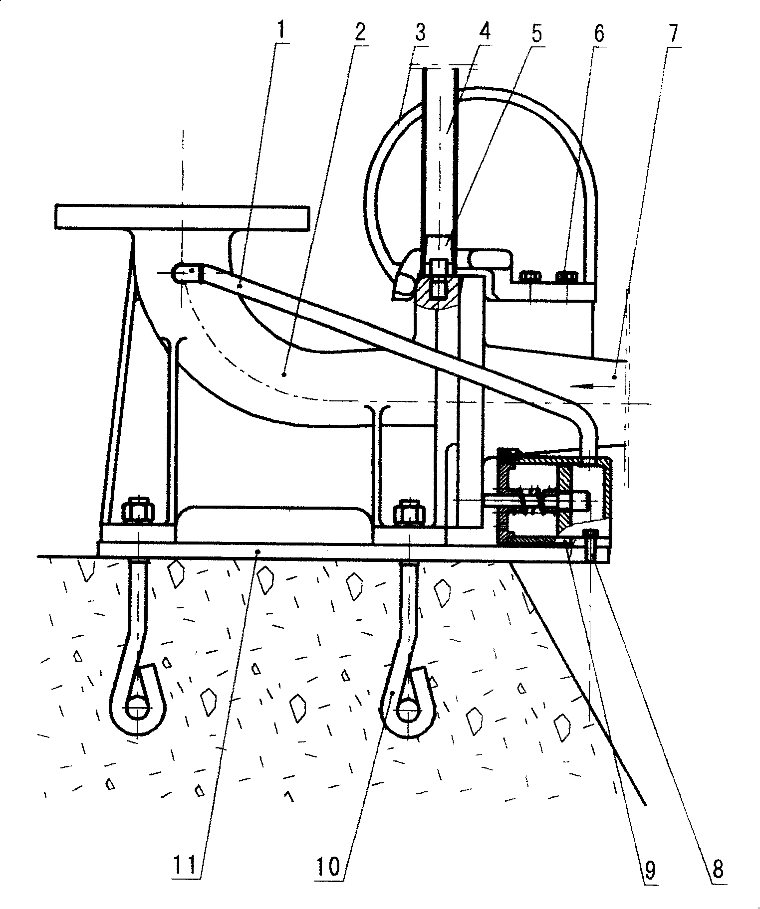
[0031] see figure 1 , in the figure: (1) is the high-pressure infusion tube, (2) is the coupling base, (3) is the pump splint, (4) is the guide rail, (5) is the positioning pin of the guide rail, (6) is the connecting screw, (7) Be a submersible pump, (8) is a connecting screw, (9) is a hydraulic cylinder, (10) is an anchor screw, and (11) is an installation floor.

[0032] Such as figure 1 As shown, the specific structure of the self-coupling and self-locking device of the high-lift submersible pump of the present invention is described as follows:

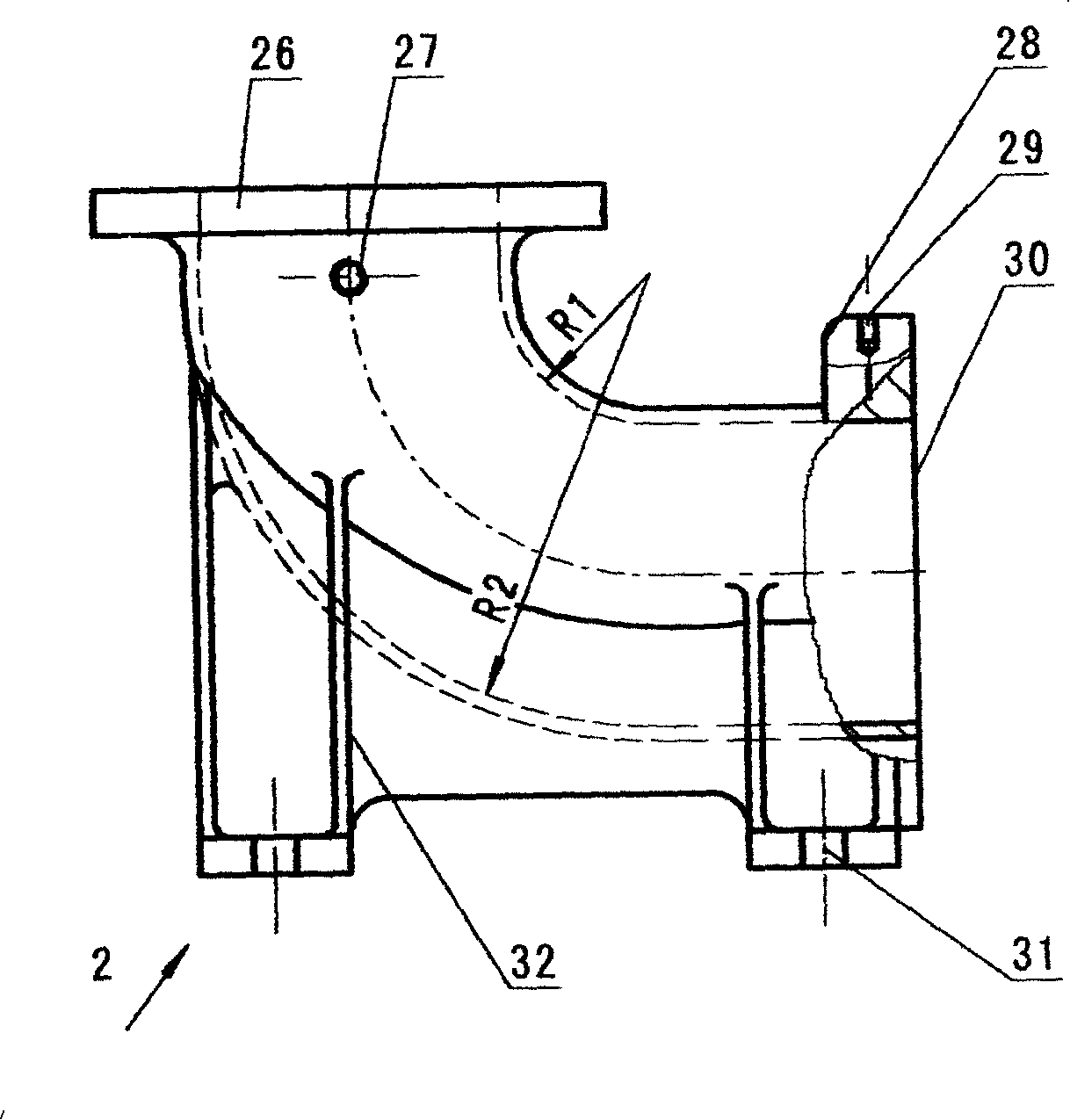
[0033] 1. One end of the high-pressure infusion tube (1) is connected to the high-pressure water intake hole (27) of the coupling base (2), and the other end is connected to the water inlet hole (18) of the hydraulic cylinder (9), such as figure 2 As shown, the high-pressure infusion tube (1) is made up of a joint (24) and a high-pressure hose (25), and the two-end joints (24) are connected to the two ends of the hose (25). T...


PUM


Abstract

The invention provides an auto-coupling and auto-locking device of a high lift diving pump and relates to a drainage device of the a diving pump. A high pressure liquid transport pipe (1) is connected with a coupling base (2) and a hydraulic cylinder (9); a coupling surface (33) of a pump splint (3) is pressed on a coupling surface (28) of a pump splint of the coupling base (2), the pump splint (3) is connected to a diving pump (7) via a bolt (6); a guide rail (4) is inserted in a guide rail pin (5) which is connected with a guide hole (29) of the coupling base (2); floor (11) on which the hydraulic cylinder (9) is arranged on is mounted on a foundation via holding down bolts (10); a steel axle (19) is provided with a piston (17) and a spring seat (15) and is sleeved with spring (14). One end of the steel axle (19) is pulled through an axle hole (42) of the steel axle (19) and supports an outlet flange of the diving pump (7). The device can avoid water loss of the coupling surface.

Description

Technical field: [0001] The self-coupling and self-locking device of a high-lift submersible pump of the invention relates to a drainage device of a submersible pump. Background technique: [0002] In the past, when the submersible pump was draining, high-pressure water was discharged from the outlet pipe of the coupling base. The high pressure of the discharged high-pressure water would cause a gap between the coupling surface of the coupling base and the coupling surface of the outlet flange of the submersible pump, which would cause Part of the water discharged by the submersible pump flows back into the drainage pool from such a gap, that is, the water discharged by the submersible pump cannot be completely discharged from the outlet pipe of the coupling base, resulting in water loss. In order to solve this problem of water loss, it is necessary to invent A device for preventing a gap generated between the above-mentioned coupling surfaces. Invention content: [0003]...

Claims


Application Information

Patent Timeline
Patent Type & Authority Applications(China)
IPC IPC(8): F04D29/00F04D29/40F04D29/60F04D13/08
Inventor 邰崇良谢新年毛骥
Owner TAIZHOU TAIFENG PUMP IND
Learn More