
Emergency calling equipment of vehicle and emergency calling system of vehicle

An emergency call and vehicle technology, which is applied in the traffic control system of road vehicles, vehicle components, traffic control systems, etc., can solve the problems that new location information cannot be obtained, location information cannot be sent to the service center, and vehicle location cannot be reported.

Inactive Publication Date: 2008-05-07
DENSO CORP
View PDF1 Cites 81 Cited by
  • Summary
  • Abstract
  • Description
  • Claims
  • Application Information

AI Technical Summary

Problems solved by technology

[0003] However, in the configuration in which the position information is received from the navigation system, for example, if the navigation system or the communication line fails, it is disadvantageous that the proper vehicle position cannot be reported to the service center
This is because even when an activation trigger for initiating an emergency call is generated (occurs), new position information located (measured) at a later (or last) time cannot be obtained from the navigation system due to the above failure, the position Information cannot be sent to the service center

Method used


Image

  • Emergency calling equipment of vehicle and emergency calling system of vehicle
  • Emergency calling equipment of vehicle and emergency calling system of vehicle
  • Emergency calling equipment of vehicle and emergency calling system of vehicle

Examples


no. 1 example

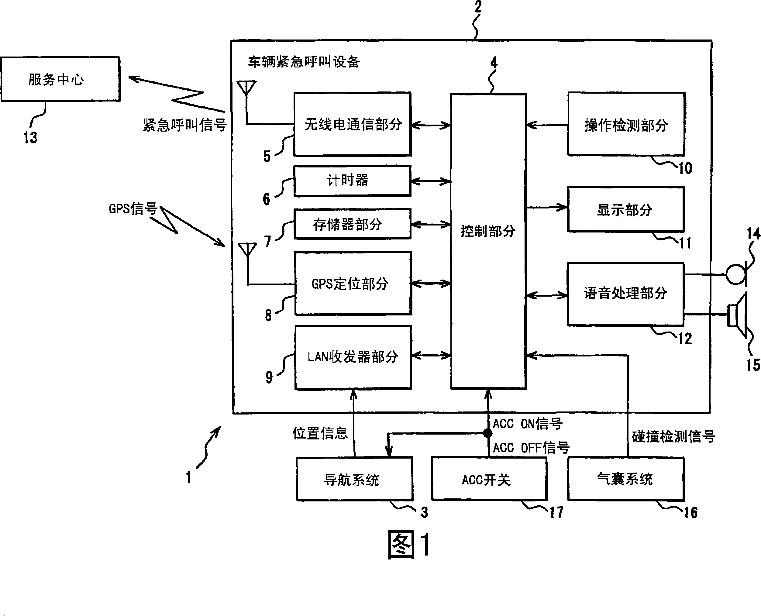
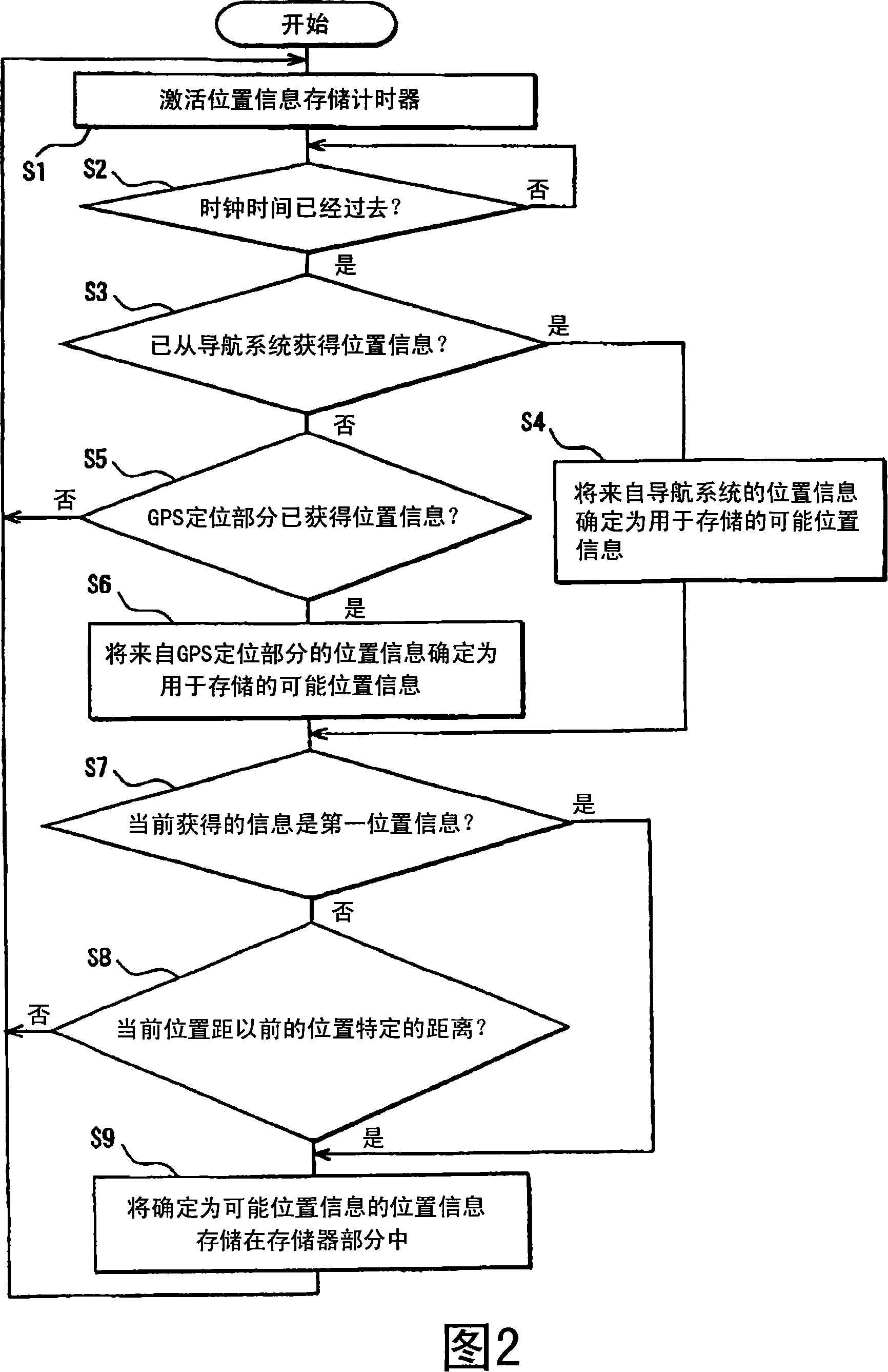
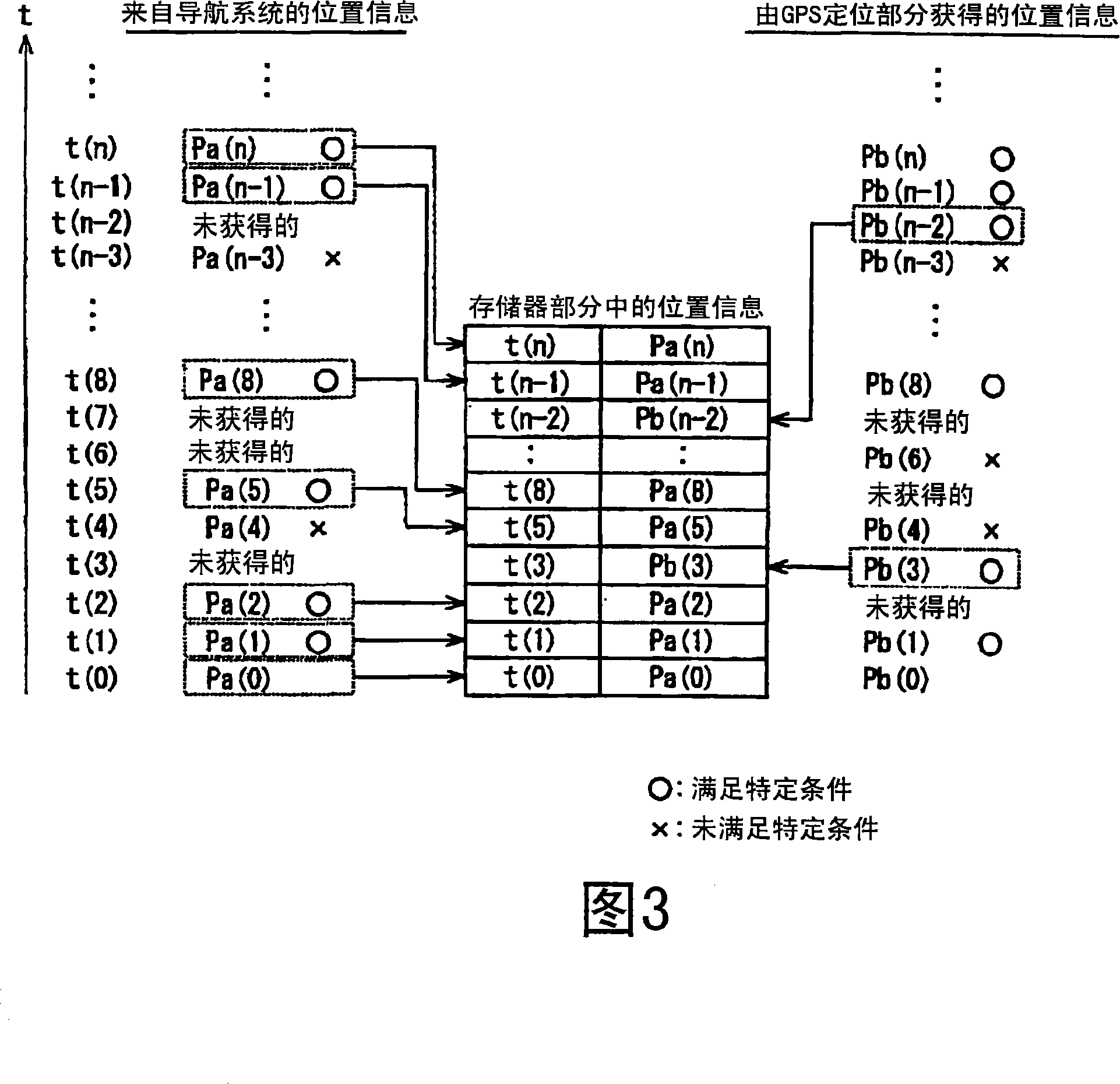
[0016] A first embodiment of the present invention will be described with reference to FIGS. 1 to 3 . The vehicle emergency call system 1 includes a vehicle emergency call device 2 and a navigation system 3 . Vehicle emergency call device 2 comprises: control part 4 (control unit of the present invention), radio communication part 5 (sending unit of the present invention), timer 6, memory part 7 (position information storage unit of the present invention), global Positioning system (GPS) positioning section 8 (positioning unit of the present invention), LAN transceiver section 9 (position information receiving unit of the present invention), operation detection section 10 , display section 11 , and voice processing section 12 .

[0017] The control section 4 is mainly composed of a CPU, and controls general operations of the vehicular emergency call device 2 . When the radio communication section 5 receives the emergency call instruction signal from the control section 4, the...

no. 2 example

[0040] Next, a second embodiment of the present invention will be described with reference to FIGS. 4 and 5 . Note that components of this embodiment similar to those of the above embodiment are denoted by the same numerals and descriptions thereof are omitted. Different components from the first embodiment are mainly described. In the above first embodiment, when the ACC ON signal is input from the ACC switch 17, a positioning instruction signal is output to the GPS positioning section 8 to activate the GPS positioning section 8. In addition, the GPS positioning section 8 is caused to receive GPS signals to periodically obtain position information. In contrast, in the second embodiment, the GPS positioning section 8 is configured to receive GPS signals to store positioning assistance information.

[0041] In other words, in the vehicle emergency call apparatus 21 of the present invention, the control section 22 outputs the positioning assistance information storage instruct...


PUM


Abstract

A vehicle emergency call device includes a position information receiving unit (9), a positioning unit (8), a position information storing unit (7), and a control unit (4). The position information receiving unit (9) obtains first position information from a navigation system (3). The positioning unit (8) obtains second position information by performing computation using positioning assist information received from a GPS satellite. The control unit (4) causes the positioning unit (8) to receive the positioning assist information while the navigation system (3) is activated. The control unit (4) causes the position information storing unit (7) to store one of the first and second position information sets. The control unit (4) transmits the one of the first and second position information sets stored in the position information storing unit (7) through a transmitting unit (5) to a service center (13) for use as an emergency call when a start trigger for starting an emergency call occurs.

Description

technical field [0001] The invention relates to a vehicle emergency call device that transmits location information to a service center for an emergency call when an activation trigger for initiating an emergency call occurs. Furthermore, the present invention relates to a vehicle emergency call system including a vehicle emergency call device and a navigation system. Background technique [0002] For example, JP-A-2001-043469 describes a vehicle emergency call device that receives and acquires position information from a navigation system, stores the position information therein. For example, when an activation trigger for initiating an emergency call occurs, the vehicle emergency call device transmits the stored location information to a service center for the emergency call. [0003] However, in a configuration in which position information is received from a navigation system, for example, if a failure occurs in the navigation system or a communication line, it is disad...

Claims


Application Information

Patent Timeline
Patent Type & Authority Applications(China)
IPC IPC(8): G08G1/127G08B25/00G08B25/01G01C21/26G01S1/02G01S5/02B60R21/00G01C21/00G01S19/03G01S19/17G01S19/48G08B25/04G08G1/0969G08G1/13
CPCG01S19/39G08G1/205
Inventor 篠田浩司
Owner DENSO CORP
Learn More