
Hand piston pump comprising a blockable distribution head which is used to distribute liquid substances

A technology of output head and piston pump, which is applied to a single handheld device, a device for liquid flow control, and liquid distribution, etc., can solve problems such as insufficient piston stroke and increased wear and tear.

Active Publication Date: 2008-04-30
MIDVESTVAKO KALMAR GMBKH
View PDF1 Cites 3 Cited by
  • Summary
  • Abstract
  • Description
  • Claims
  • Application Information

AI Technical Summary

Problems solved by technology

When the output head is skewed, the piston stroke is insufficient, resulting in multiple runs, which means that an undesirably excessive amount needs to be supplied
In addition, increased wear

Method used


Image

  • Hand piston pump comprising a blockable distribution head which is used to distribute liquid substances
  • Hand piston pump comprising a blockable distribution head which is used to distribute liquid substances

Examples


Embodiment Construction

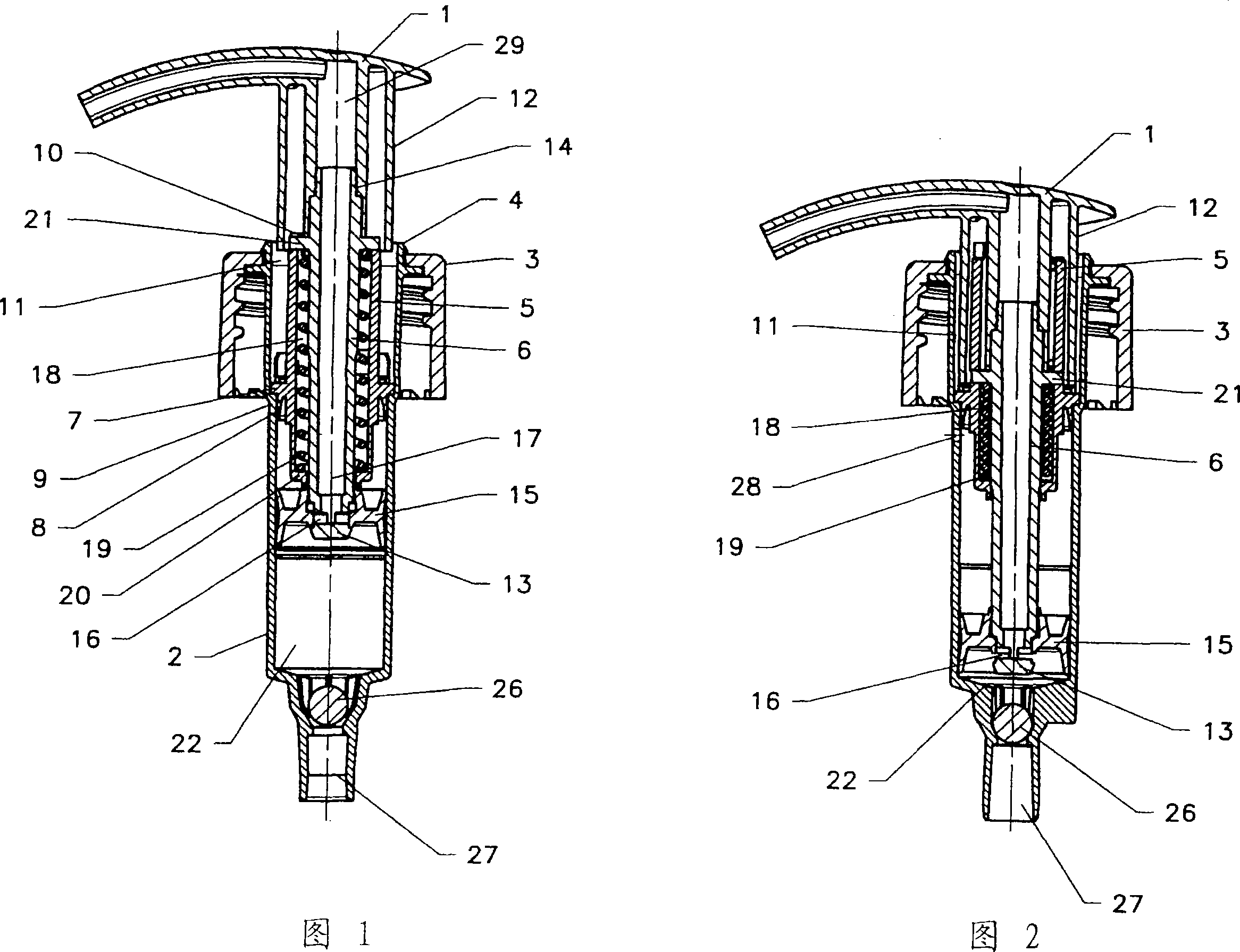
[0014] The invention relates to a manual piston pump for dispensing fluid substances with a lockable dispensing head 1 . The manual piston pump comprises a cylinder 2, the upper end of which is fixedly connected to a locking member 3 which can be fixed to the mouthpiece of a container (not shown) in order to receive the liquid or cream to be delivered. substance. In this case, the locking element 3 is provided with a thread as closing element. The cylinder 2 may have a ring 4 acting as an upper termination.

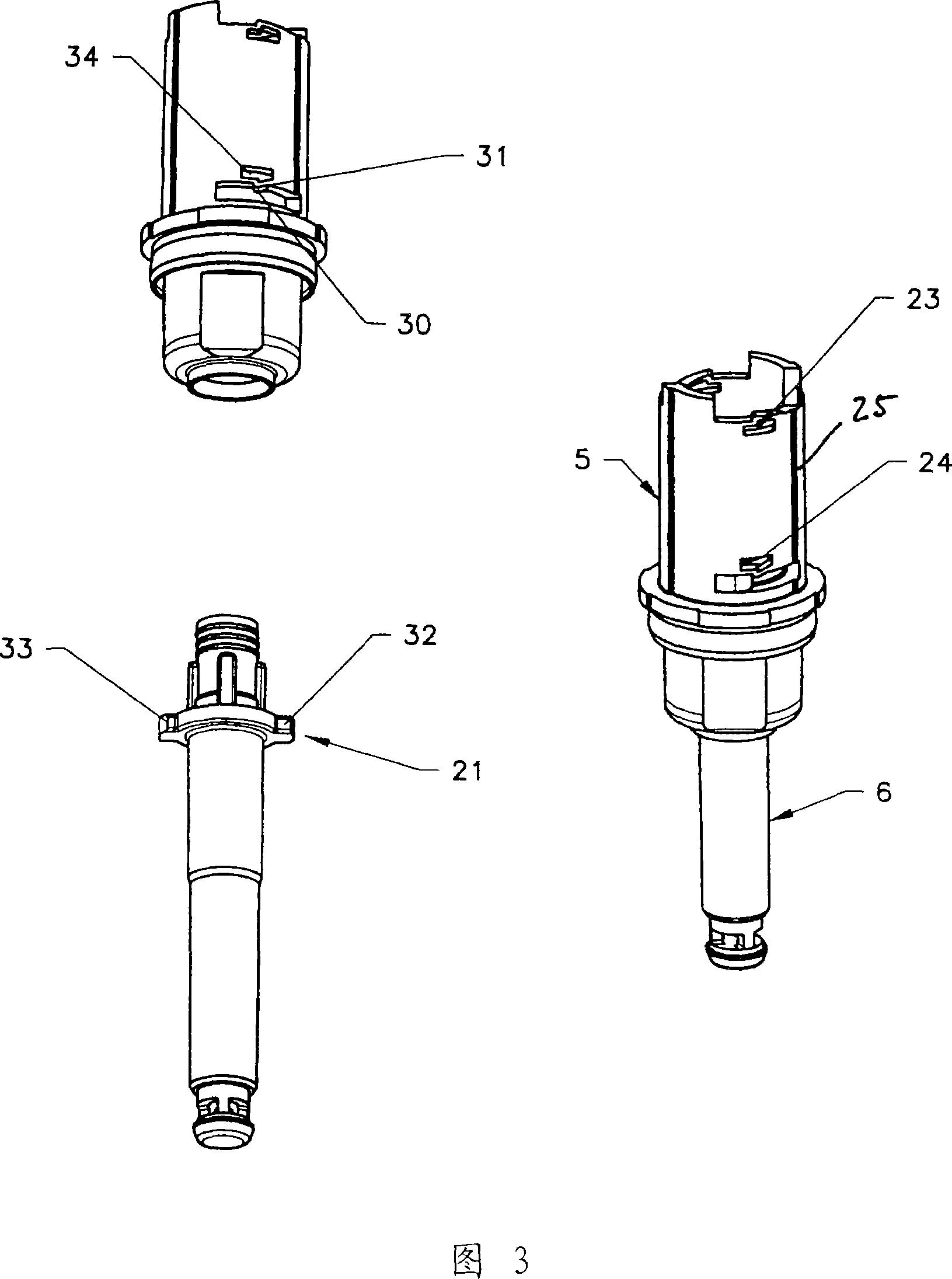
[0015] An inner locking sleeve 5 is fixedly positioned within the cylinder 2 forming a cylinder channel through which a hollow piston rod 6 can pass. The locking sleeve 5 is preferably clamped inside the cylinder 2 , for which purpose the locking sleeve 5 can have a clamping ring 7 with a sealing lip 8 and can be supported against a shoulder 9 of the cylinder 2 . The locking sleeve 5 extends along the length of the upper part of the cylinder 2, the upper end 10 of the ...


PUM


Abstract

The invention relates to a hand piston pump comprising a blockable distribution head for the distribution of liquid substances. Said pump comprises a cylinder, an internal locking sleeve for a hollow piston rod and which forms a cylinder leadthrough, whereby one end thereof extends into the pump chamber of the cylinder and the other end thereof supports the distribution head which is provided with an external shaft section, a spring which presses the piston rod into a rest position, in relation to the cylinder, in an outward direction. Said piston rod can be lowered by pressure on the distribution head in order to distribute a substance, counter to the spring force thereof, and also comprises a device which is used to block the distribution head, which comprises at least one locking element which can be placed in contact with the locking sleeve. The locking sleeve (5) forms an inner cage (18) with the piston rod (6) in order to receive the spring (19) which presses one side against the base (20) of the locking sleeve (5) and the other side against the locking element (21) which is provided on the piston rod (6). The locking sleeve (5) forms, with the cylinder (2) along the upper section and which is oriented towards the distribution head (1), a guiding channel (11 ) which is parallel to the piston rod (6) as a sliding path for the external shaft section (12) of the distribution head (1).

Description

technical field [0001] The invention relates to a manual piston pump with a lockable delivery head for delivering fluid substances as described in the preamble of claim 1 . Background technique [0002] DE 33 16 308 A1 discloses a hand pump having an output head mounted on the shaft of the pump itself. In a normal resting state, the shaft protrudes beyond the hollow body portion forming the base of the pump. The lower end of the hollow movable shaft projects into the interior of the cavity of the body portion and is urged outwardly by a spring acting on its lower end. Additionally, a locking sleeve is fixedly connected to the hollow body portion. The pump has one or more cams or teeth or protrusions to lock the delivery head to the locking sleeve. Furthermore, the pump has one or more sealing inserts which seal the output head from the outside atmosphere when it is locked to the base body of the pump. [0003] The disadvantage that accompanies the stated advantages of a ...

Claims


Application Information

Patent Timeline
IPC IPC(8): B05B11/00B67D99/00B67D7/58
CPCB05B11/3023B05B11/306B05B11/3074B05B11/0044B05B11/1023B05B11/106B05B11/1059B05B11/1067B05B11/1074
Inventor 罗伯特·芬豪泽托马斯·霍曼
Owner MIDVESTVAKO KALMAR GMBKH
Learn More