
Underpan structure of wind cooling electric generating set

A generator set and chassis technology, which is applied to the frame of the engine, engine components, machines/engines, etc., can solve the problems of insufficient ventilation structure of the generator set, achieve the simplification of the test program, reduce the overall noise level, and reduce the consumption of manpower and material resources Effect

Active Publication Date: 2008-04-09
WUXI KIPOR POWER CO LTD
View PDF1 Cites 11 Cited by
  • Summary
  • Abstract
  • Description
  • Claims
  • Application Information

AI Technical Summary

Problems solved by technology

[0004] There are deficiencies in the ventilation structure of the generating set involved in this document

Method used


Image

  • Underpan structure of wind cooling electric generating set
  • Underpan structure of wind cooling electric generating set
  • Underpan structure of wind cooling electric generating set

Examples


Embodiment Construction

[0030] The present invention will be further described below in conjunction with accompanying drawing and specific embodiment:

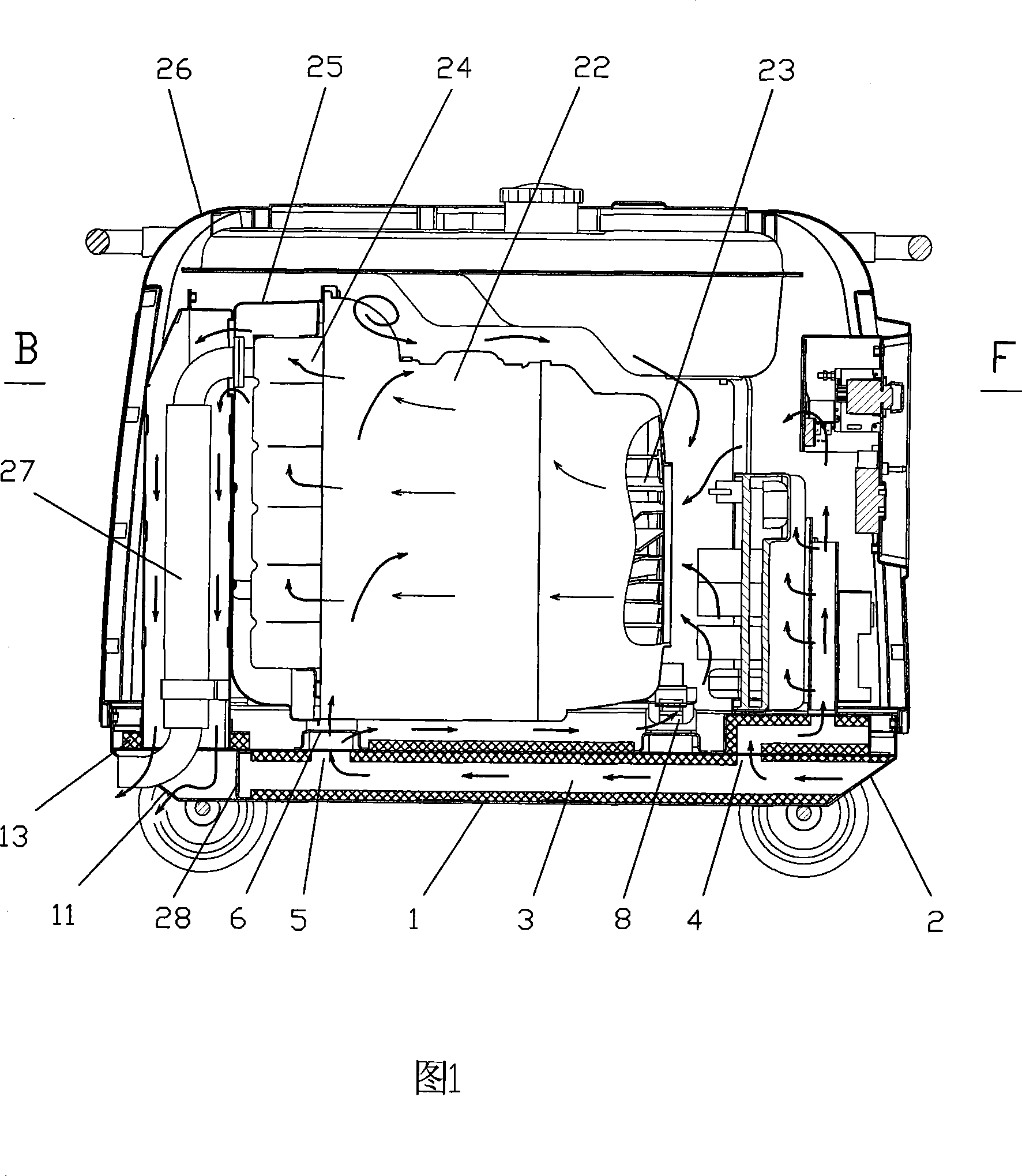
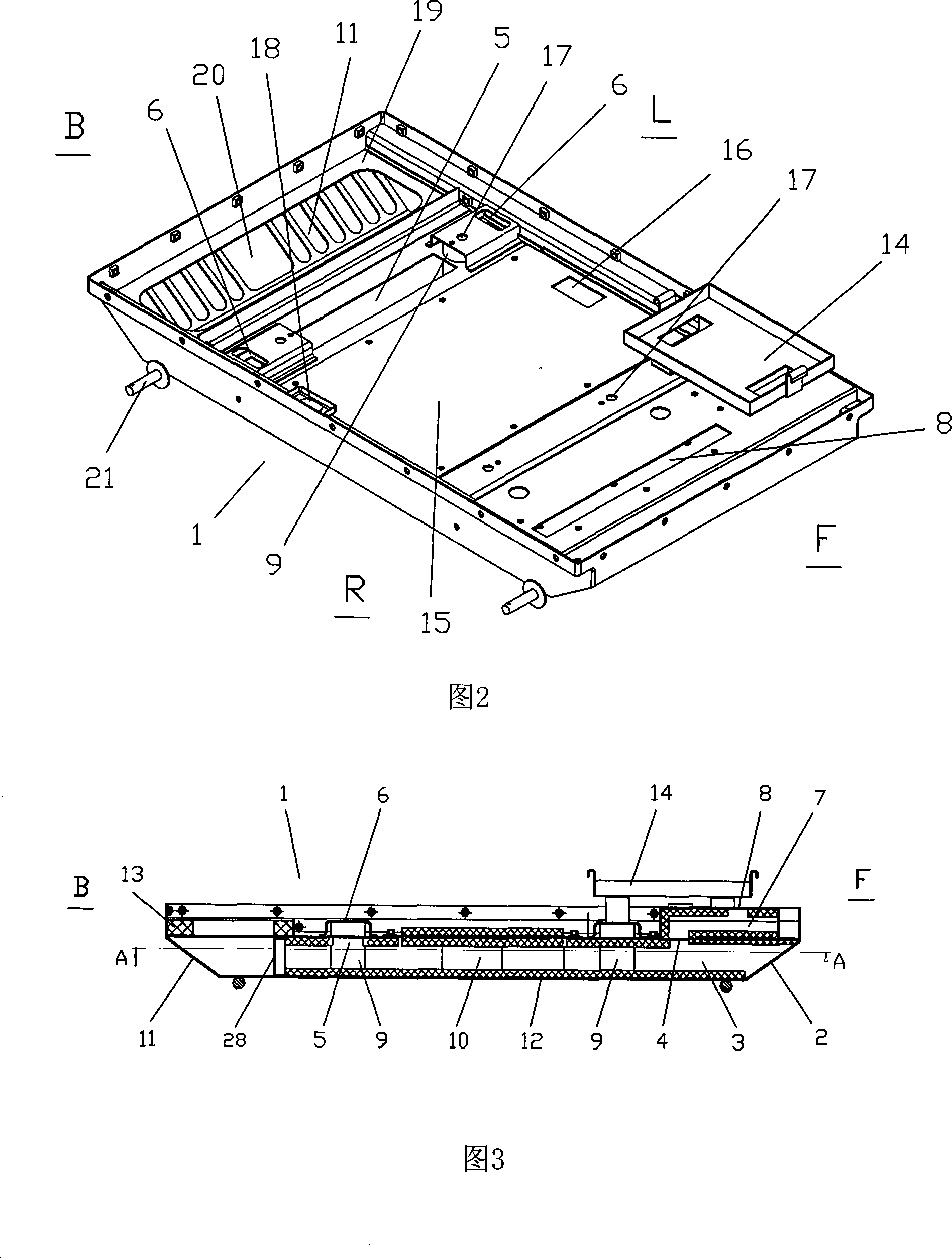
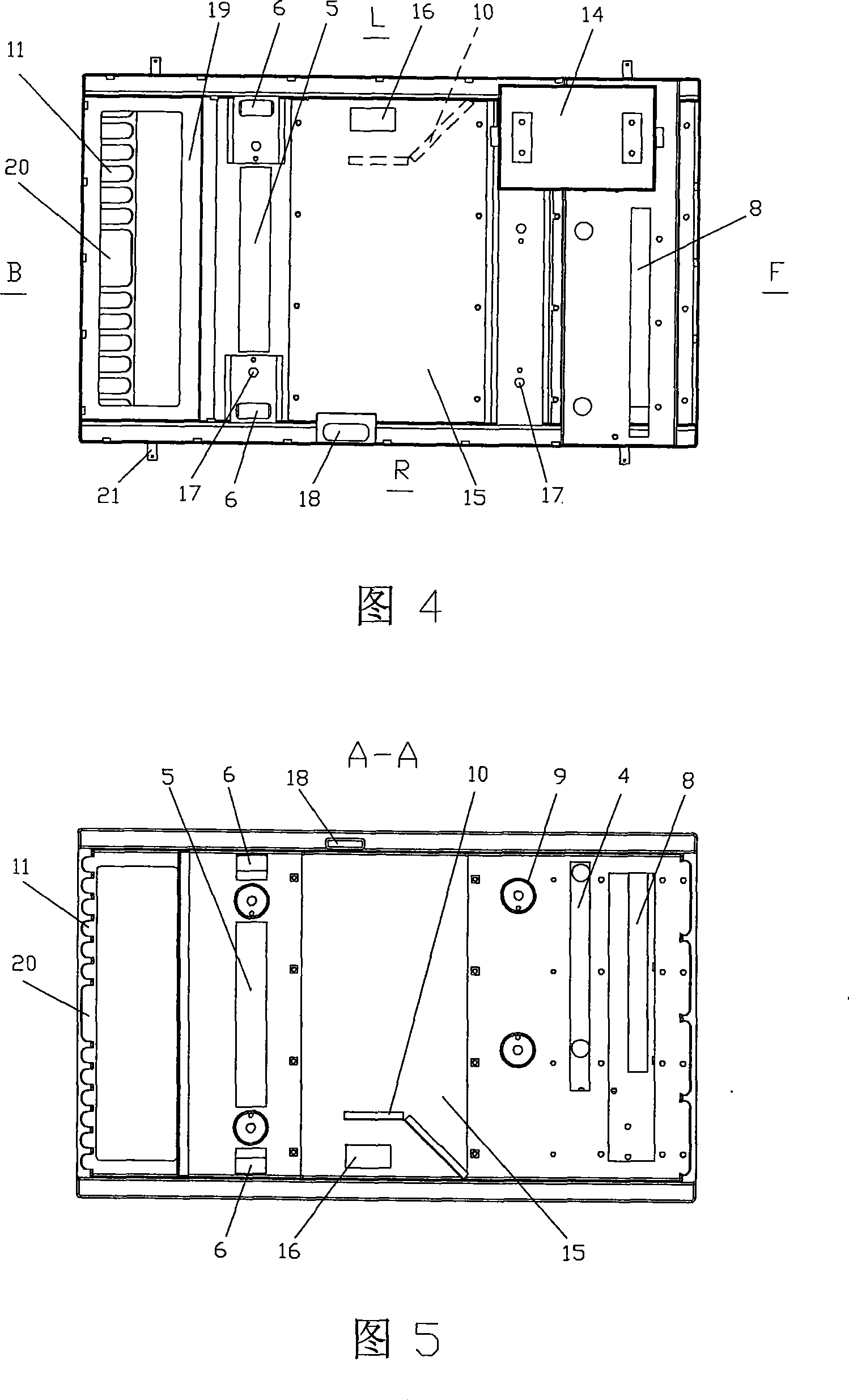
[0031] The ventilation structure of the generator set of the present invention mainly includes a chassis 1, an air inlet 2, a main air duct 3, a first air distribution port 4, a second air distribution port 5, a third air distribution port 6, an air guide duct 7, an air guide duct outlet 8, Tubular column 9, noise screen plate 10, air outlet 11, sound-absorbing sponge 12, gasket 13, battery holder 14, main air duct cover 15, power distribution port 16, power bracket installation hole 17, oil funnel 18, exhaust Sealing surface 19, exhaust pipe through hole 20, wheel shaft 21, engine generator assembly 22, engine fan 23, muffler 24, muffler cover 25, hood assembly 26, exhaust pipe 27, partition 28, front end F, Rear B, left L, right R.

[0032] As shown in Figures 1 to 8, the chassis 1 is composed of stamped and punched steel plate components, and the...


PUM


Abstract

The invention relates to a chassis structure of a wind cooling generator unit. The invention is characterized in that the front end F of the chassis is provided with a wind inlet; a main wind duct is horizontally arranged in the wind inlet; the end of the main wind duct is provided with a clapboard which hermetically comparts the main wind duct and an wind outlet; the rear end of the chassis is provided with the wind outlet, with the exhaust direction pointing to a oblique lower part; the main wind duct is respectively provided with a first wind distributing port, a second wind distributing port and a third wind distributing port which are communicated in a casing assembly; one end of a wind guide duct is communicated with the first wind distributing port and the other end of the wind guide port is communicated with the outlet of the wind guide duct. The invention sufficiently utilizes the absorption and dispersion function of the ground to the noise, causes the noise field with strong directivity outwards radiated by the wind outlet of the generator unit to be attenuated and weakened and the noise of the whole machine is reduced; the arrangement of a plurality of wind distributing ports can ensure that all parts in the generator unit casing can be suitably cooled, the service life of corresponding parts can be prolonged, and the stability of the unit in long-term operation can be ensured.

Description

technical field [0001] The invention relates to a chassis structure of an air-cooled generator set, and in particular belongs to the technical field of mobile power bases. Background technique [0002] In the prior art, the chassis of the air-cooled internal combustion generator set is usually provided with only air inlets and few air outlets on the chassis, and the cooling air is mostly discharged from the air duct opened on the upper casing of the unit. In addition, after some air-cooled generator sets introduce cooling air from the outside, they lack the necessary wind direction guidance and air volume distribution means, and the cold air utilization efficiency is low. [0003] The Chinese patent number is ZL02143431.X, and the patent document published on April 20, 2005 discloses an invention patent named "Engine Generator Set". The inlet and the external air inlet on the generator side, while the exhaust outlet is located on the upper part of the soundproof box of the ...

Claims


Application Information

Patent Timeline
IPC IPC(8): F02B63/04F02B77/00F01P5/06F16M3/00
Inventor 肖亨琳
Owner WUXI KIPOR POWER CO LTD
Learn More