Receiver for optical communications, comprising a nonlinear equaliser

A receiver and equalizer technology, applied in the field of receivers, can solve problems such as communication deterioration and signal reduction

Inactive Publication Date: 2008-03-12
UNIV POLITECNICA DE CATALUNYA
View PDF1 Cites 4 Cited by
  • Summary
  • Abstract
  • Description
  • Claims
  • Application Information

AI Technical Summary

Problems solved by technology

Among the linear distortions there is chromatic dispersion, as is e.g. described in Govind P. Agrawal, John Wiley & Son Publisher, "Fiber Optic Communication Systems", since some wavelengths travel faster than others and thus the chromatic dispersion reduces the detected signal, when the fiber coupling length and bandwidth exceed the limit of the required detection parameters, the digital pulse is extended and the communication is deteriorated

Method used


Image

  • Receiver for optical communications, comprising a nonlinear equaliser

Examples


Embodiment Construction

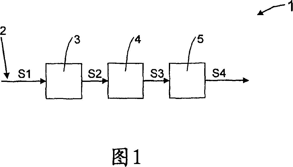
[0021] As can be seen in FIG. 1 , the optical communication receiver 1 basically comprises a first element 2 of an optical fiber drop line for transmitting an information-carrying signal S1, a photodetector unit 3, a nonlinear equalizer unit 4 and a terminal processor unit 5.

[0022] The optical signal S1 carrier of the information transmitted along the optical fiber 2 and originating from a long-distance optical transmitter (not shown) is input into the photodetector unit 3, and the photodetector unit 3 generates an electrical signal S2, and the electrical signal 2 is input to nonlinear equalizer unit 4. This non-linear equalizer unit 4 immediately preceding the unit produces the S3 signal from the S2 signal, which is then equalized and filtered by the terminal processor unit 5, which produces the output signal S4.

[0023] The main object of the invention is the included nonlinear equalizer unit 4 . The nonlinear equalizer unit 4 produces a signal S3 that is mathematicall...


PUM


Abstract

The present development includes a first element of an optical fibre entrance by which an information carrying signal is transmitted, an optical detector block, a non-linear equalizer block and a final processor block. The development includes an electrical non-linear equalizer block, connecting the output of the optical detector block and the input of the final processor block that compensates the quadratic non-linear characteristic of the optical detector block. Both blocks thus may present a more linear joint characteristic between the electrical field envelope of the information carrying signal in the optical fibre and the electrical signal. Consequently, the final processor block can compensate, in a more effective form, for the linear distortions that the information carrying signal suffers in the transmission through the fibre. The result may be an optical receiver with non-linear compensation of the photo-detection process and with approximate linear compensation of the linear distortions of the optical fibre transmission.

Description

technical field [0001] The invention relates to a receiver for optical communication comprising a first element of an optical fiber drop through which an information signal propagates, a light detection unit, a non-linear electrical equalizer unit and a terminal processor unit. Background technique [0002] The realization of communication systems using optical fibers as transmission channels has only been possible due to the progress made in the related fields of laser beams and optical fibers, which are fundamentally derived from the characteristics of light. [0003] An optical fiber communication system is composed of a transmitting unit, also known as a transmitter or an optical transmitter, in its more basic structure. The transmitting unit has the function of converting information electrical signals into information signals in the form of light; this The optical transmission channel, that is, the optical fiber; and the receiving unit that has the function of converti...

Claims


Application Information

Patent Timeline
Patent Type & Authority Applications(China)
IPC IPC(8): H04B10/18H04B10/158H04B10/69
CPCH04B10/6971
Inventor 何塞普·普拉特·戈马皮耶路易吉·波焦利尼
Owner UNIV POLITECNICA DE CATALUNYA
Why Eureka
Try Eureka