
Vacuum valve

A technology of vacuum valve and vacuum zone, applied in sliding valve, valve details, valve device and other directions, can solve the problems of complex structure, large structure, high cost, etc., and achieve the effect of high torsional rigidity

Inactive Publication Date: 2008-01-23
VAT HLDG AG
View PDF7 Cites 19 Cited by
  • Summary
  • Abstract
  • Description
  • Claims
  • Application Information

AI Technical Summary

Problems solved by technology

This construction is more complex and thus more expensive and results in a larger construction

Method used


Image

  • Vacuum valve
  • Vacuum valve
  • Vacuum valve

Examples


Embodiment Construction

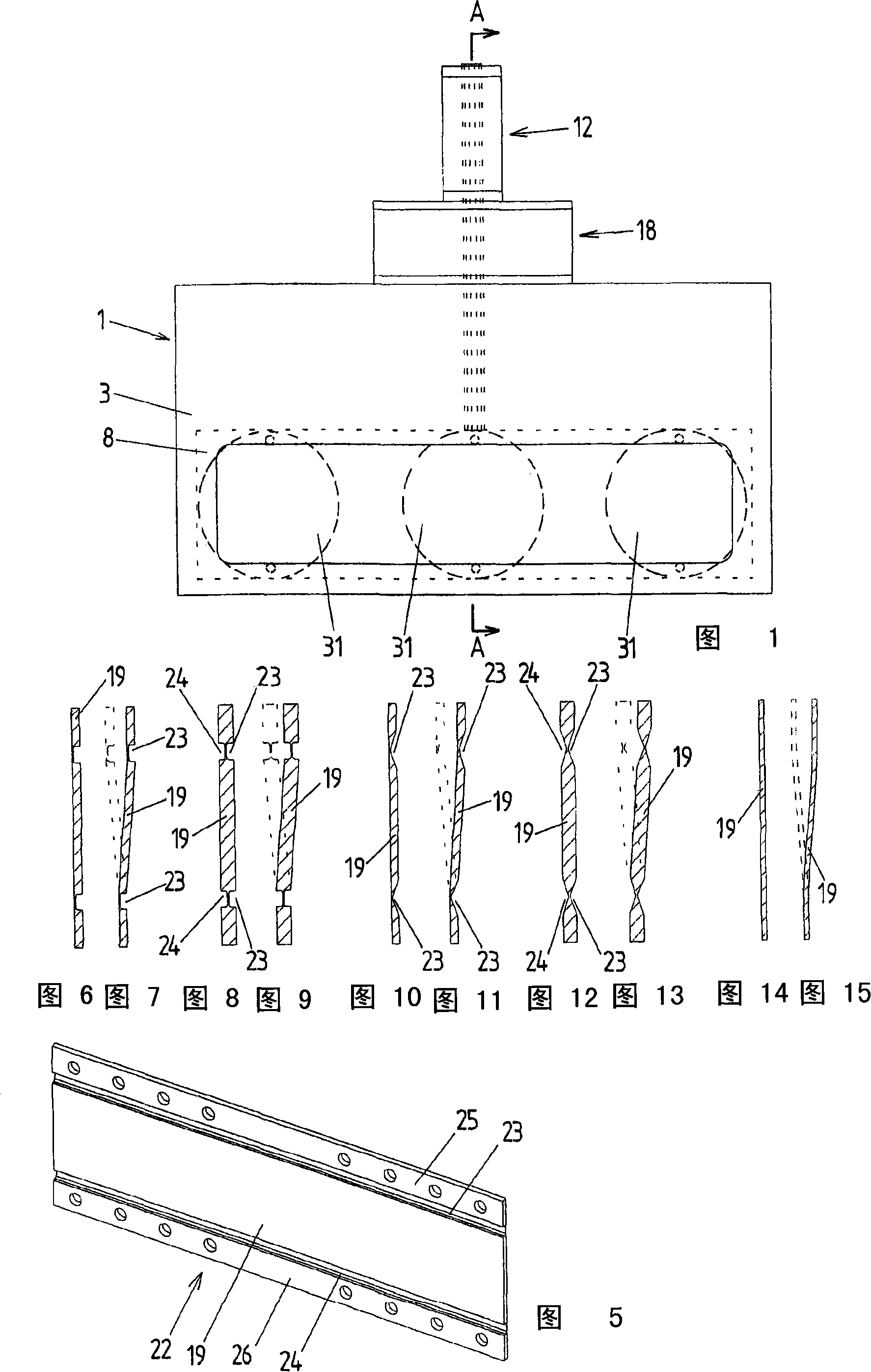
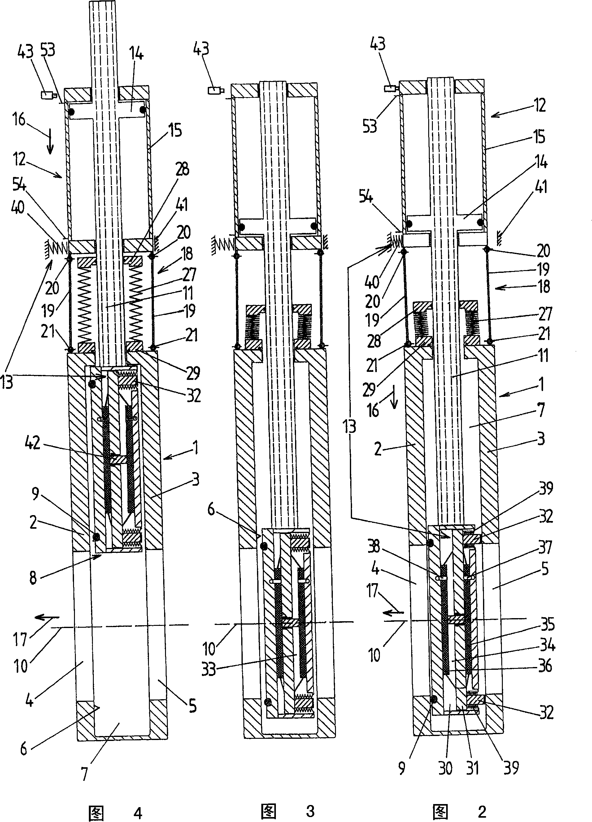
[0034] A first exemplary embodiment of the invention is schematically shown in FIGS. 1 to 7 . The vacuum valve has a valve body 1 which, in the exemplary embodiment shown, is designed as a housing. The opposing walls 2 , 3 are pierced by an inlet opening forming a valve opening 4 and an outlet opening 5 . The valve opening 4 is surrounded by a valve seat 6 formed by a sealing surface on the inner side of the wall 2 .

[0035] In the exemplary embodiment shown, the longitudinal axis 10 of the valve opening coincides with the longitudinal axis of the outlet opening 5 , as is preferred.

[0036] The inner space 7 of the valve body 1 forms the vacuum region of the vacuum valve, in which inner space 7 a valve plate 8 is arranged. In the closed position of the valve plate 8 , it is pressed against the valve seat 6 , wherein the seal 9 of the valve plate bears against the valve seat 6 .

[0037] For example, the seal 9 can also be arranged on the valve seat 6 and a sealing surface...


PUM


Abstract

A vacuum valve comprises a valve body with a valve opening, a valve plate which is adjustable from an open position, in which it releases the valve opening, to an intermediate position, in which it covers the valve opening but is lifted from the valve seat, into a closed position in which it contacts the valve seat, and from the closed position to the intermediate position into the open position, a valve rod carrying the valve plate, a transverse drive unit by which the valve plate can be displaced in a transverse adjusting direction extending transverse to the longitudinal axis of the valve opening, a longitudinal drive unit by which the valve plate can be displaced in a longitudinal adjusting direction extending parallel to the longitudinal axis of the valve opening and opposite the longitudinal adjusting direction, and a guide device by which the transverse drive unit is guided so as to be displaceable relative to the valve body parallel to the longitudinal adjusting direction. The transverse drive unit is displaced relative to the valve body parallel to the longitudinal adjusting direction when the valve plate is adjusted from its intermediate position to its closed position and from its closed position to its intermediate position.

Description

technical field [0001] The invention relates to a vacuum valve, which comprises a valve body having a valve hole and a valve seat surrounding the valve hole, a valve plate, a valve rod carrying the valve plate, a transverse drive unit and a longitudinal drive unit, Where the valve bore has a longitudinal axis, the valve plate is adjustable from an open position through an intermediate position into a closed position against the valve seat and from the closed position through the intermediate position into the In the open position, in which the valve plate releases the valve hole, in the intermediate position the valve plate covers the valve hole but is lifted from the valve seat, and wherein by means of the The transverse drive unit can adjust the valve plate from its open position into its intermediate position in a transverse adjustment direction transverse to the longitudinal axis of the valve bore and out of its intermediate position opposite to the transverse adjustment d...

Claims


Application Information

Patent Timeline
Patent Type & Authority Applications(China)
IPC IPC(8): F16K3/18F16K3/316F16K31/122F16K51/02
CPCF16K3/18F16K51/02F16K3/314F16K31/122
Inventor H·迪戴尔M·肖恩
Owner VAT HLDG AG
Learn More