
Synchro clutch for washing machine

A technology for clutches and washing machines, applied in the field of transmission systems and synchronous clutches, to achieve the effect of simplifying transmission mechanisms and manufacturing costs

Inactive Publication Date: 2008-01-23
QINGDAO TECHN COLLEGE
View PDF0 Cites 4 Cited by
  • Summary
  • Abstract
  • Description
  • Claims
  • Application Information

AI Technical Summary

Problems solved by technology

[0004] The purpose of the present invention is to overcome the disadvantages and deficiencies of the current pulsator washing machine that uses the complex deceleration clutch as the transmission system to the pulsator washing machine, and to provide a key component of the transmission system of the fully automatic pulsator washing machine——for the washing machine. synchronized clutch

Method used


Image

  • Synchro clutch for washing machine
  • Synchro clutch for washing machine
  • Synchro clutch for washing machine

Examples


Embodiment Construction

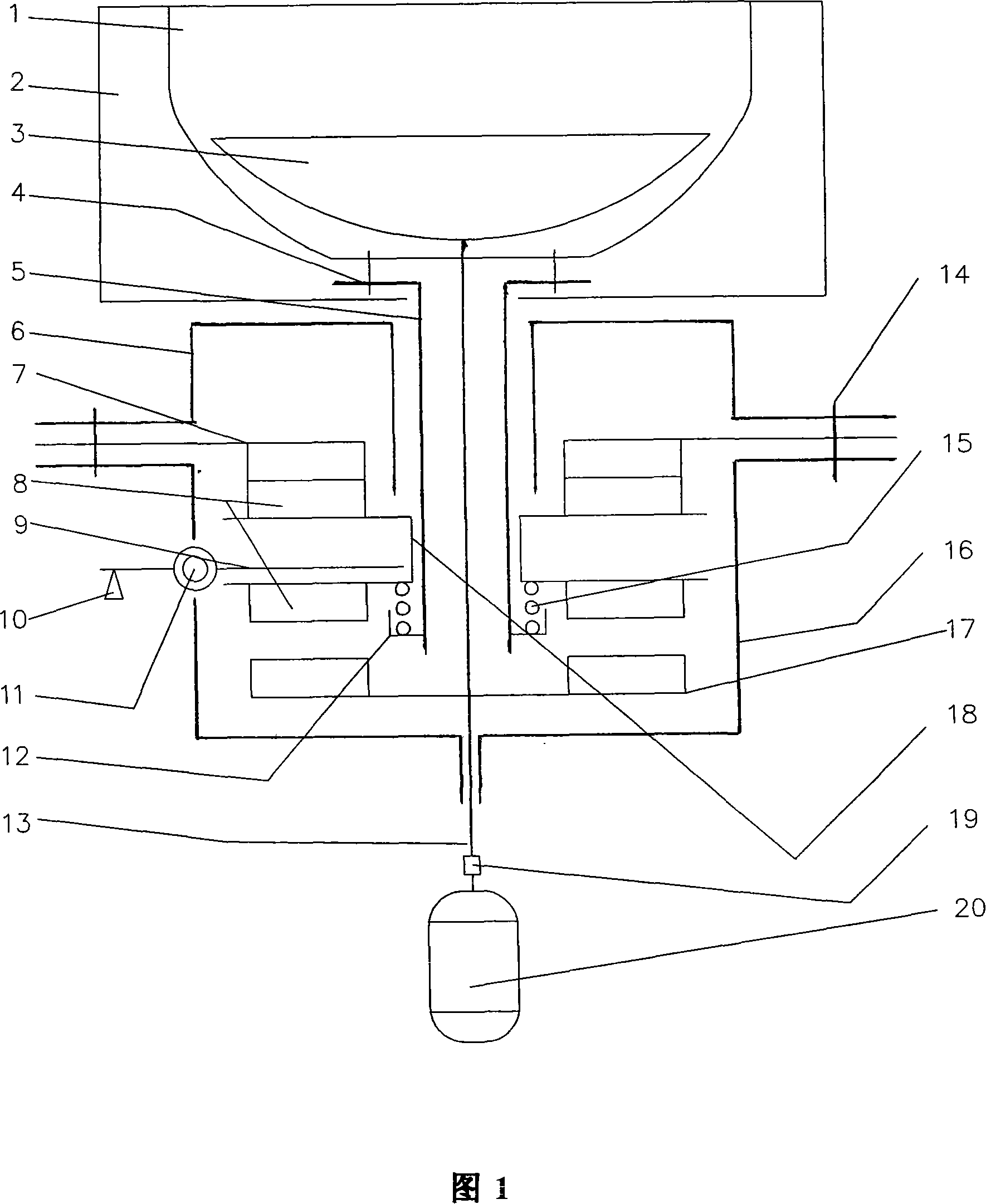
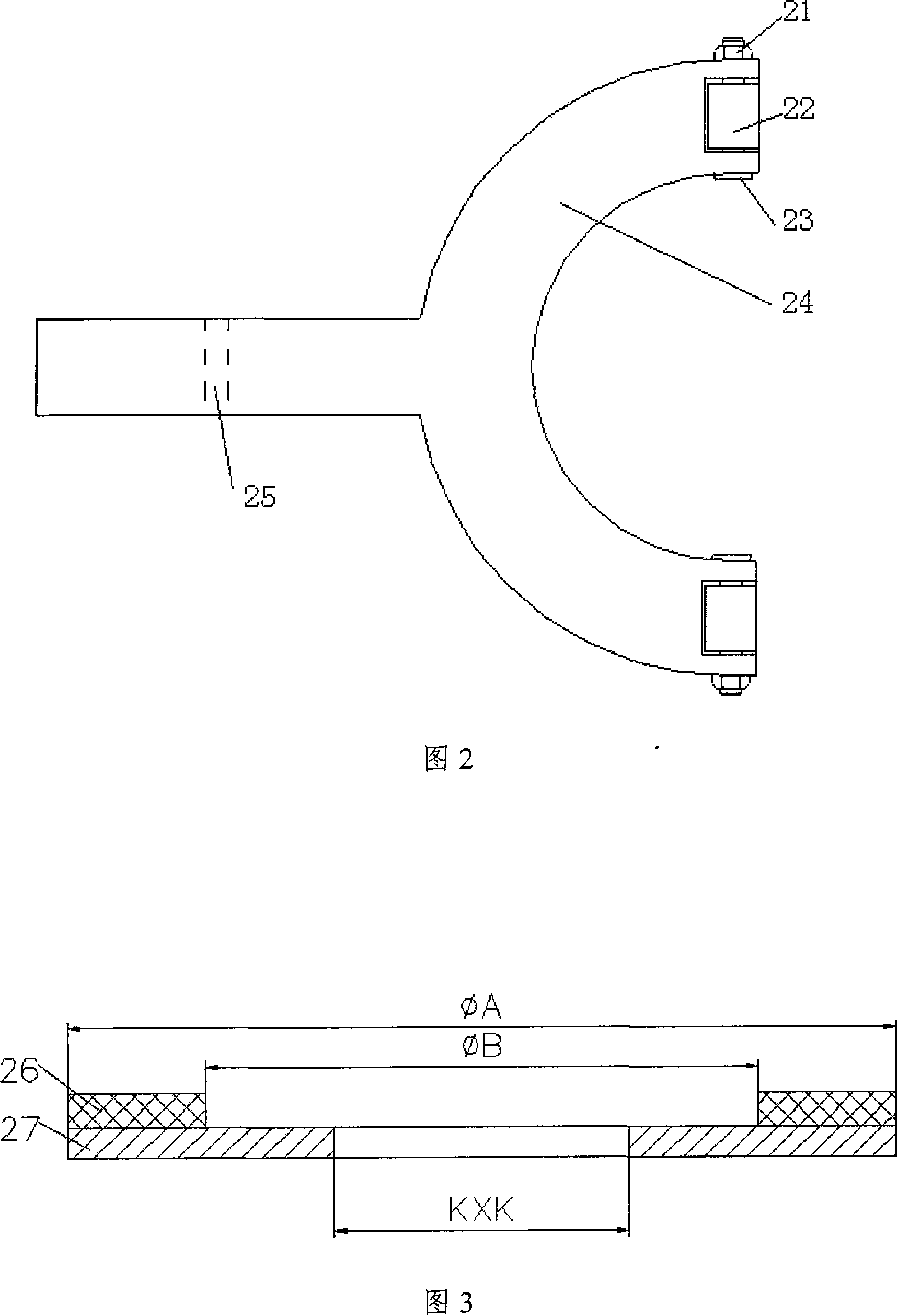
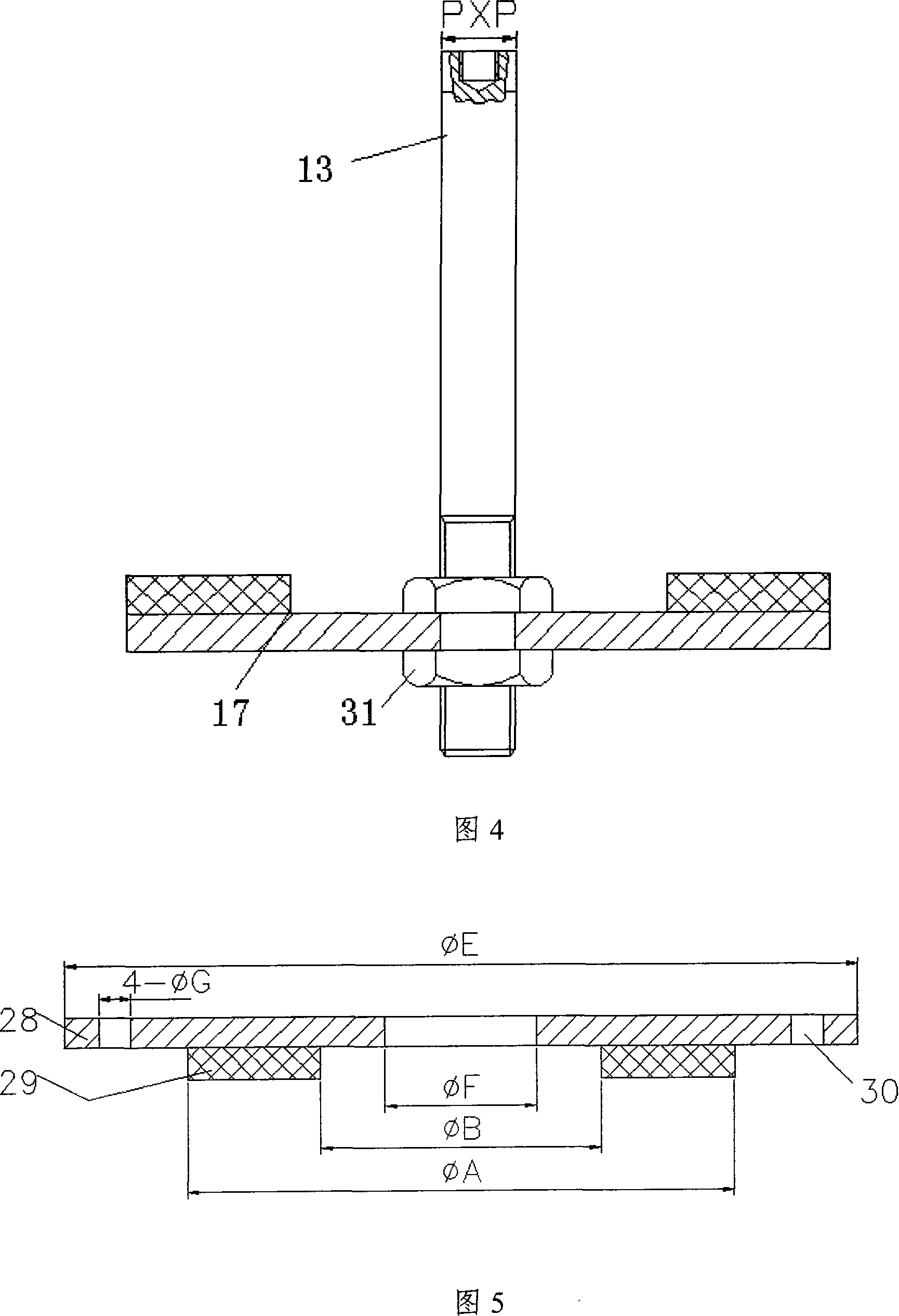
[0029] As shown in Fig. 1 to Fig. 8, the present invention is characterized in that in the upper casing 6 and the lower casing 16 that are covered together, from the bottom to the top of the lower casing 16, the bottom of the lower casing 16 is fixed on the The dehydration friction plate assembly 17 on the washing shaft 13 and the sliding sleeve 18 connected with the dehydration shaft 5 by splines are respectively fixed with a movable friction plate 8 on the upper and lower sides, and the sliding sleeve 18 is pressed against the compression spring 15 on the dehydration shaft 5. And the adjustment nut 12 threaded with the dehydration shaft 5 below it, the washing friction plate assembly 7 fixed at the junction of the upper housing 6 and the lower housing 16 and the washing friction plate 29 on it correspond to the movable friction plate 8, And the roller 22 (two) on the fork body 24 of the shift fork assembly 9 that links to each other with the drainage tractor 10 is against the...


PUM


Abstract

The invention relates to a synchronous clutch for washers. In the up and lower casing that are closing each other, from down to up sequentially the following parts are provided: a dewatering friction plate assembly fixed on the washing shaft and near to the bottom of the casing, movable friction plates fixed respectively on the upper and lower part of the slide sleeve that are connected with the dewatering shaft by a spline; washing friction plates that are fixed on washing friction plate assembly located at the joining site of the upper and lower casing and corresponding with the movable friction plates; a roller that is connected with the drainage dragger and passes into the shift fork assembly located at the perimeter of the lower casing through a pin shaft is put against the bottom of the outer cylindrical face of the spline in the slide sleeve. The invention is of novel, reasonable and simple structure. A wave-wheel washer using the invention as a drive system can realize the optimal combination of different washing, rinsing and dewatering, so as to save power, water, wash clean, achieve low wear and high dewatering rate, and can greatly simplify the complex drive mechanism and high manufacturing cost of wave-wheel washers.

Description

technical field [0001] The invention relates to a transmission system of a pulsator fully automatic washing machine—a synchronous clutch for the washing machine. Background technique [0002] The transmission system of the traditional fully automatic pulsator washing machine uses a deceleration clutch, which has a complex structure, high cost, high failure rate, and difficult maintenance (this is because the gears in the deceleration clutch cannot be replaced and repaired), so the deceleration clutch is damaged. After that, it is generally not repaired, only replaced. The cost of replacing the deceleration clutch is generally between 250 and 300 yuan. Like this, both increased the user's economic burden, caused the waste of the waste product of a large amount of deceleration clutches again. [0003] In addition, with the wide application of frequency conversion technology, it will eventually replace the existing constant speed system of the existing pulsator fully automati...

Claims


Application Information

Patent Timeline
IPC IPC(8): D06F37/30D06F17/08
Inventor 杨欣
Owner QINGDAO TECHN COLLEGE
Learn More