Break detecting device of sewing machine needle

A detection device and sewing machine needle technology, applied in the direction of sewing machine control devices, sewing machine components, sewing equipment, etc., can solve the problems of difficult needle breaking judgment, mutual interference, serious bending degree, etc., and achieve the effect of simple structure

Inactive Publication Date: 2008-01-23
PEGASUS SEWING MASCH MFG CO LTD
View PDF1 Cites 7 Cited by
  • Summary
  • Abstract
  • Description
  • Claims
  • Application Information

AI Technical Summary

Problems solved by technology

[0004] However, in the existing sewing machine needle break detection device, only a single proximity sensor is arranged under the needle plate, which can only be applied to a sewing machine for one needle.
In addition, if multiple proximity sensors are arranged side by side under the needle plate for application to multi-needle sewing machines, the proximity sensors interfere with each other due to the influence of high-frequency magnetic fields, making it difficult to judge broken needles.
In addition, other than the right needle, sometimes the distance from the needle plate to the tip of the needle is long when it is at the bottom dead center of the needle, and the degree of bending is severe, and the needle may touch the proximity sensor when the needle is lowered.

Method used


Image

  • Break detecting device of sewing machine needle
  • Break detecting device of sewing machine needle
  • Break detecting device of sewing machine needle

Examples


Embodiment Construction

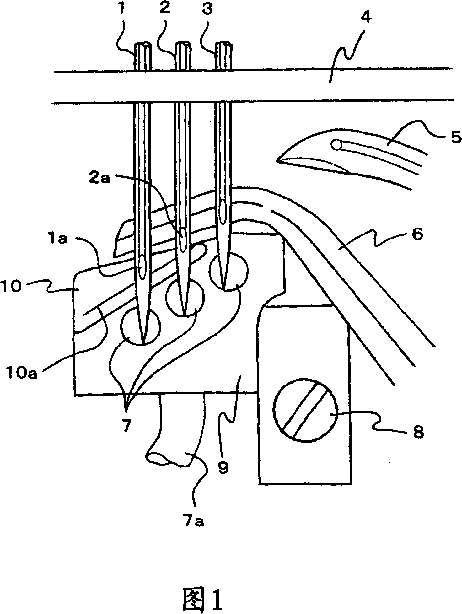
[0012] Embodiments of the present invention will be described below based on the drawings. Three needles arranged side by side (left needle 1, middle needle 2, and right needle 3) reciprocate up and down in conjunction with the rotation of the main shaft, and their front ends pass through the needle plate 4 when descending. Below the needle plate 4, the looper 5 swings left and right in conjunction with the rotation of the main shaft. As shown in FIG. In addition, a needle guard 6 is disposed behind each needle that reaches the bottom dead center. The needle guard 6 is configured to be connected to a known forward and backward movement mechanism, and advances to approach the rear of the needle when the needle starts to rise.

[0013] Below the needle plate 4, a proximity sensor 7 for detecting the presence or absence of a needle is provided. This time, in order to apply it to a three-needle sewing machine, three proximity sensors are arranged side by side on the left and rig...


PUM


Abstract

Provided is a needle breaking detection apparatus applied on the multi-needle sewing machine whose needles do not contact with the sensor besides the right needle. The needle breaking detection apparatus for the sewing machine has an approaching sensor disposed below the needle plate in order to detect the existence of the needle and further judge the needle breaking based on the existence of the needle. A plurality of approaching sensors are arranged based on the numbers of the left-and-right needle disposed in parallel in the needle break detection apparatus for the sewing machine. Amplifiers are connected to the approaching sensors with the function of interference prevention. The needle breaking is judged by comparing the predetermined needle numbers and the total needle numbers detected by the approaching sensor.

Description

technical field [0001] The present invention relates to a sewing machine needle break detection device that detects a needle break that occurs during sewing of a sewing machine. Background technique [0002] As a conventional sewing machine needle break detection device, there is known a sewing machine needle that is provided with a proximity sensor disposed below the needle plate to detect the presence or absence of a needle, and judges that a needle is broken based on the detection of the presence or absence of a needle by the proximity sensor. Breakage detection device (for example, refer to Patent Document 1). [0003] [Patent Document 1] Japanese Unexamined Patent Publication No. 11-221392 (page 2-3, Fig. 1-2) [0004] However, in the existing sewing machine needle breakage detection device, only a single proximity sensor is arranged under the needle plate, which can only be applied to a sewing machine for one needle. In addition, if a plurality of proximity sensors a...

Claims


Application Information

Patent Timeline
Patent Type & Authority Applications(China)
IPC IPC(8): D05B69/36
Inventor 川人俊夫高田隆山崎彻
Owner PEGASUS SEWING MASCH MFG CO LTD
Why Eureka
Try Eureka