
Secure power supply jack with ratchet wheel clamping machine

A technology of clamping mechanism and safety power supply, applied in the direction of circuits, electrical components, parts of connecting devices, etc., can solve the problems of electric danger, non-compliance with double-sided contact, affecting the effect of use, that is, lifespan, etc., and achieves easy operation habits. Effect

Inactive Publication Date: 2008-01-16
张文辉
View PDF1 Cites 7 Cited by
  • Summary
  • Abstract
  • Description
  • Claims
  • Application Information

AI Technical Summary

Problems solved by technology

In order to solve the reliability, the thickness of the clamping copper sheet is continuously increased and the first-class material is selected to enhance the elasticity. Although the problems of safety and close contact have been solved to varying degrees, there are still many deficiencies, such as the patent I invented a few years ago. The number is 00 2 29339.0 (rotary safety power socket), strictly speaking, it has not been solved perfectly for these two shortcomings. The plug can be easily pulled out when it reaches the 0 position, and the hole is still dangerously charged
Second: Structurally, the plug is in single-sided collision contact, which is prone to arc damage to the surface of the plug, affecting the next use effect, that is, life, and does not meet the requirements of some countries that require double-sided contact.
Its operational safety and reliability are still dangerous

Method used


Image

  • Secure power supply jack with ratchet wheel clamping machine
  • Secure power supply jack with ratchet wheel clamping machine
  • Secure power supply jack with ratchet wheel clamping machine

Examples


specific Embodiment

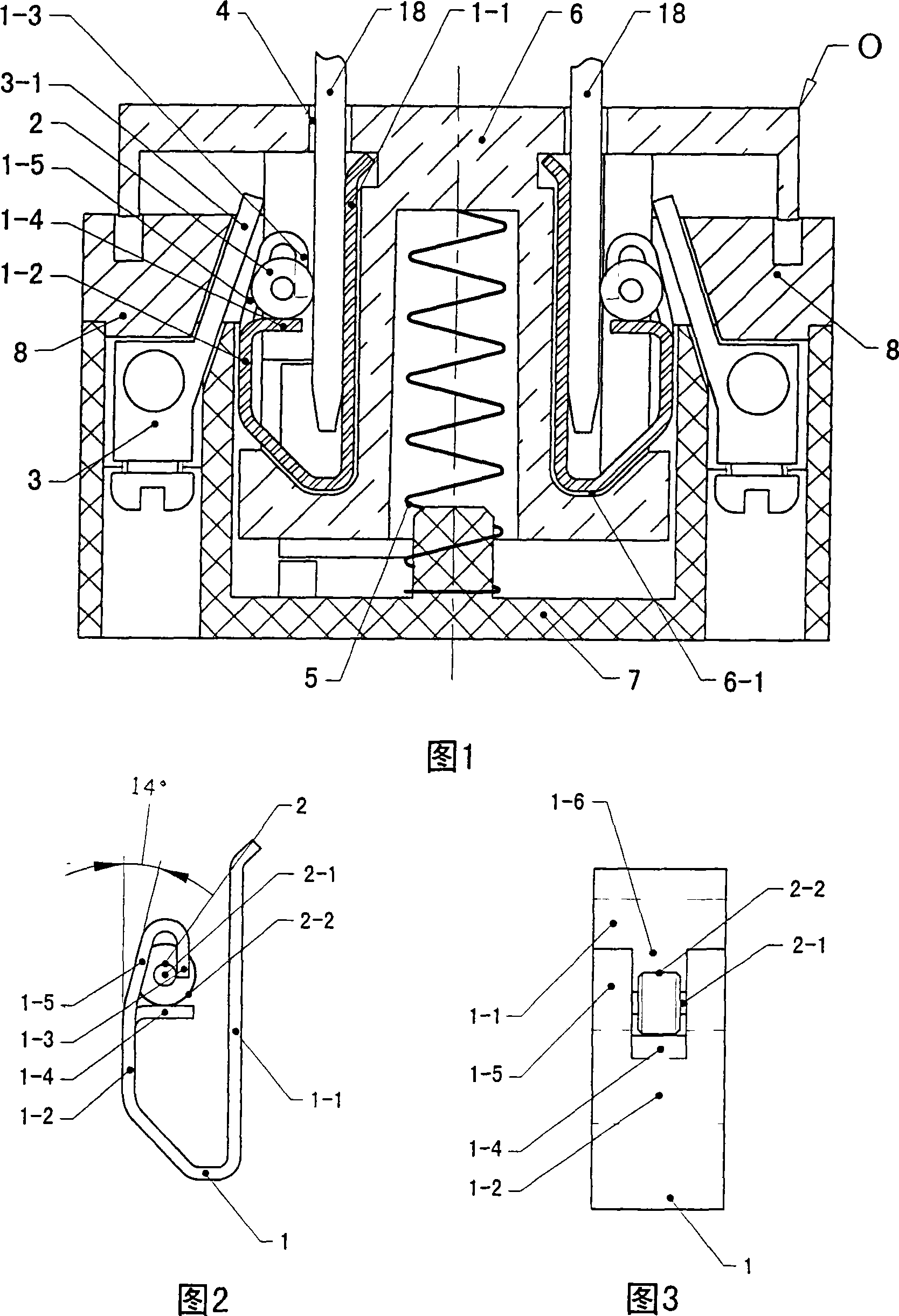
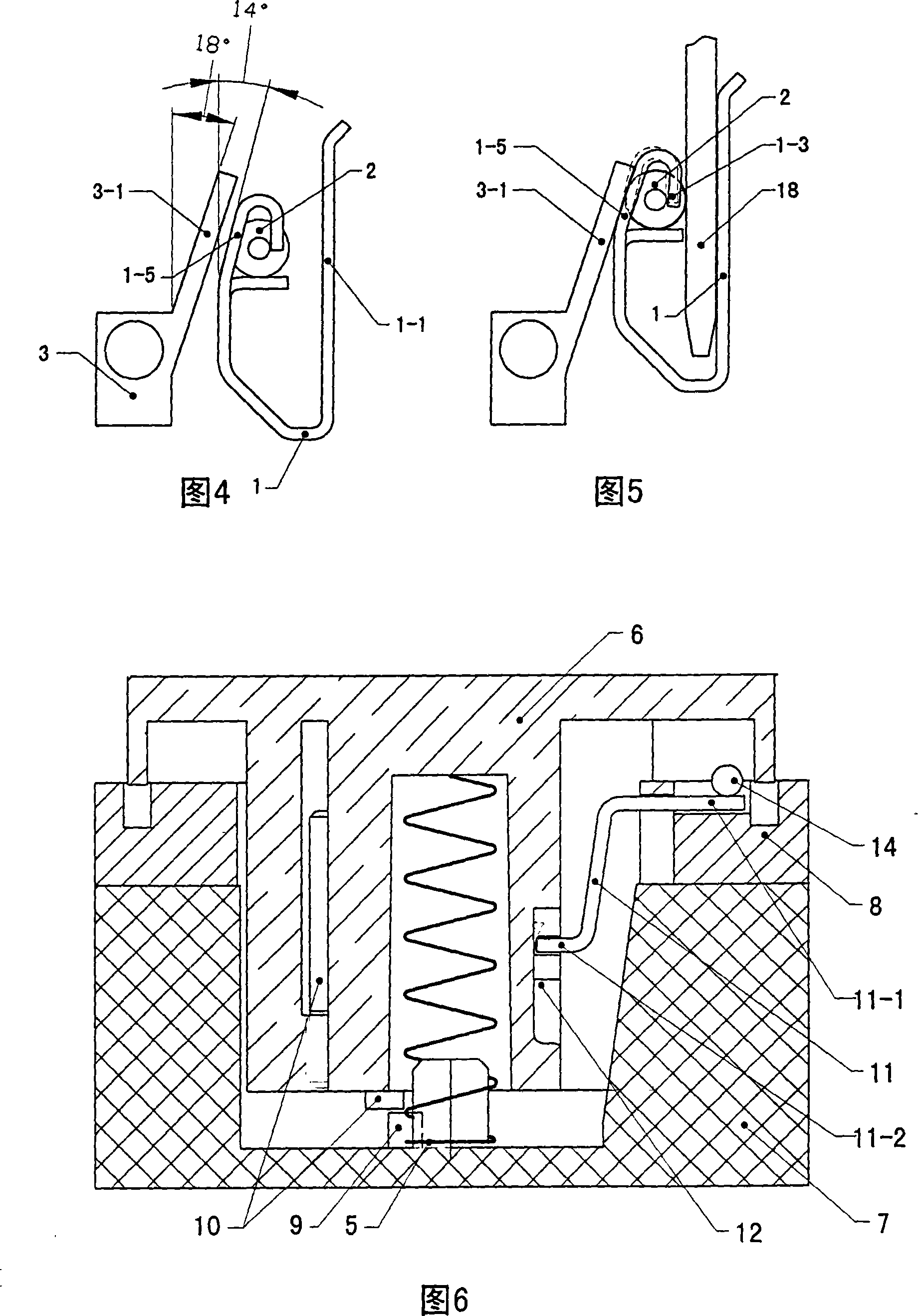
[0023] Fig. 1 is a cross-sectional view of the structure of the present invention, Fig. 2 is a schematic structural view of a conductive clip with a ratchet clamping mechanism, Fig. 3 is a right view of a conductive clip with a ratchet clamping mechanism: the present invention includes a seat shell 7, a shell cover 8, a hollow core Body 6, the support spring 5 between the hollow core body 6 and the seat shell 7, the power terminal 3, the jack 4 and the conductive contact piece in the jack, the conductive contact piece is the conductive clip 1 of the ratchet clamping mechanism, the conductive clip It is ear-shaped, and the conductive sheet 3-1 of the power terminal is inclined at an angle inside the shell cover. The upper part of the conductive sheet is fixed by the shell cover 8 so that the angle does not change. The conductive clip is placed between the inclined conductive sheet 3-1 and the hollow core. 6 forms a right-angled trapezoidal space, embedded in the groove 6-1 of th...


PUM


Abstract

The invention provides a safety outlet with a ratchet clamping mechanism, and comprises an outlet shell, a shell cover, a hollow core body, a plug hole and electric contacts in the plug hole. A positioning mechanism is arranged between the hollow core body and the shell cover, an open ear-shape conducting clip is provided on the electric contacts, electric contacts of power connecting terminals lean inwards with a certain angle in the shell cover, the upper part of the electric contacts are fixed by the shell cover, the conducting clip is equipped in the right-angle trapezoid space formed by the leaned electric contacts and the hollow core body and is embedded in the trench of the hollow core body, the vertical arm of the conducting clip is positioned inside the plug hole, the ear-shape profile side of the conducting clip is positioned outside the plug hole, the upper part of the ear-shape profile side of the conducting clip is an inclined plane leaning in the same direction of the electric contacts, and a downward barb is provided on the opening of the ear-shape profile side. A ratchet fovea is formed by the barb, the upper part of the ear-shape profile side and a lower lateral bearing plate, a longitudinal opening is cut on the barb and the upper part of the ear-shape profile, the ratchet is equipped in the ratchet fovea, and the flange is positioned on the longitudinal opening.

Description

technical field [0001] The invention relates to a safety power socket with a ratchet clamping mechanism, which is used in all places where electricity is used. Background technique [0002] In the field of power sockets, in order to solve the problems of safety and reliability, for example: rotary safety sockets, sockets with safety protection doors, etc. have been born to solve electric shock protection. In order to solve the reliability, the thickness of the clamping copper sheet is continuously increased and the first-class material is selected to enhance the elasticity. Although the problems of safety and close contact have been solved to varying degrees, there are still many deficiencies, such as the patent I invented a few years ago. The number is 00 2 29339.0 (rotary safety power socket), strictly speaking, it has not been solved perfectly for these two shortcomings. The plug can be easily pulled out when it reaches the 0 position, and the hole is still dangerously c...

Claims


Application Information

Patent Timeline
IPC IPC(8): H01R13/639H01R13/629
Inventor 张文辉
Owner 张文辉
Learn More