Electrical relay

A relay, bottom plane technology, applied in the direction of electromagnetic relays, relays, electromagnetic relay details, etc.

Active Publication Date: 2008-01-16
TYCO ELECTRONICS AUSTRIA
View PDF4 Cites 11 Cited by
  • Summary
  • Abstract
  • Description
  • Claims
  • Application Information

AI Technical Summary

Problems solved by technology

As is known, this situation presents the same problem in bistable magnetic systems, since said armature is fixed and does not enter the region where considerable opening forces are only directed towards the tightening movement of the armature applied at one end

Method used


Image

  • Electrical relay
  • Electrical relay
  • Electrical relay

Examples


Embodiment Construction

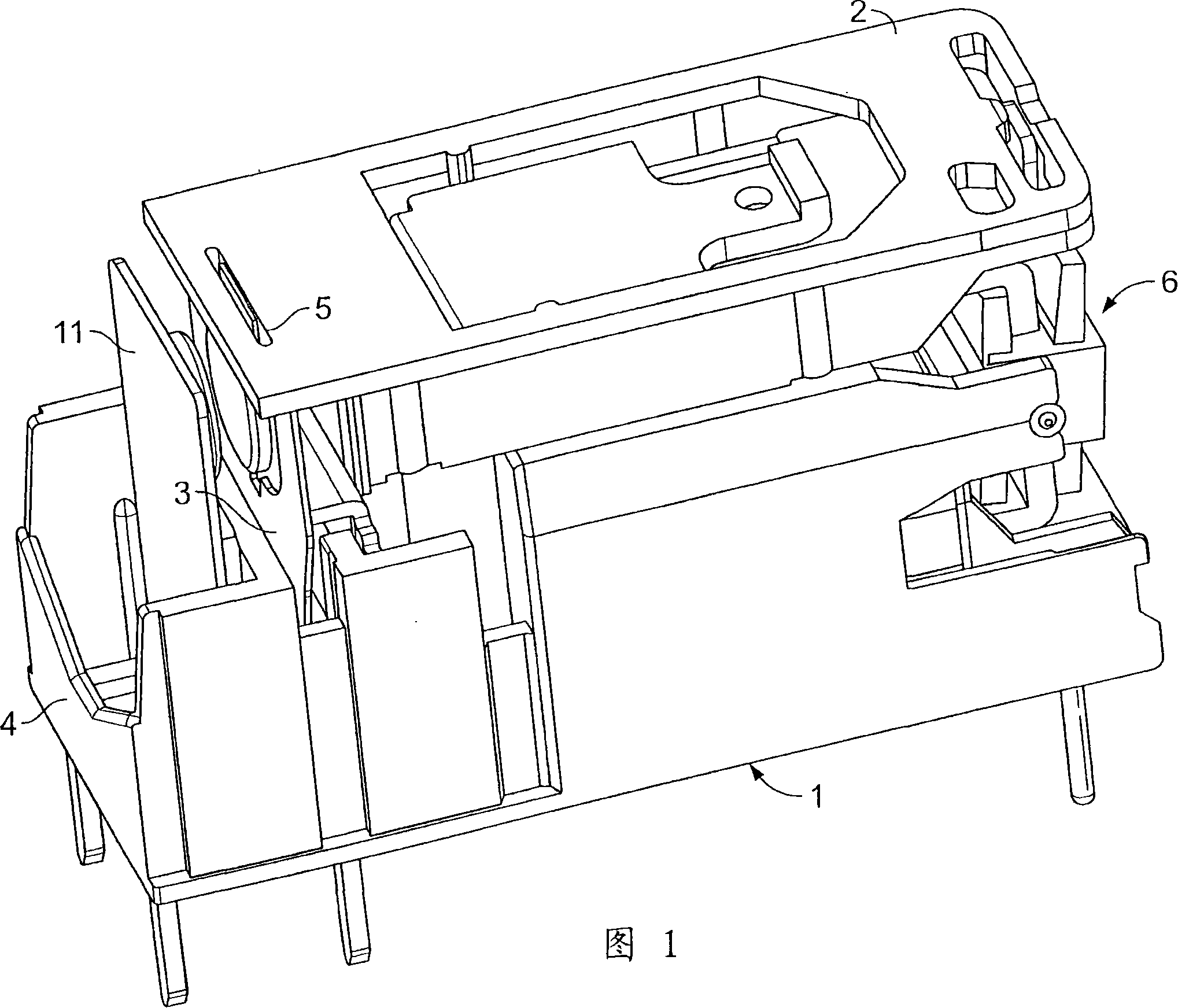
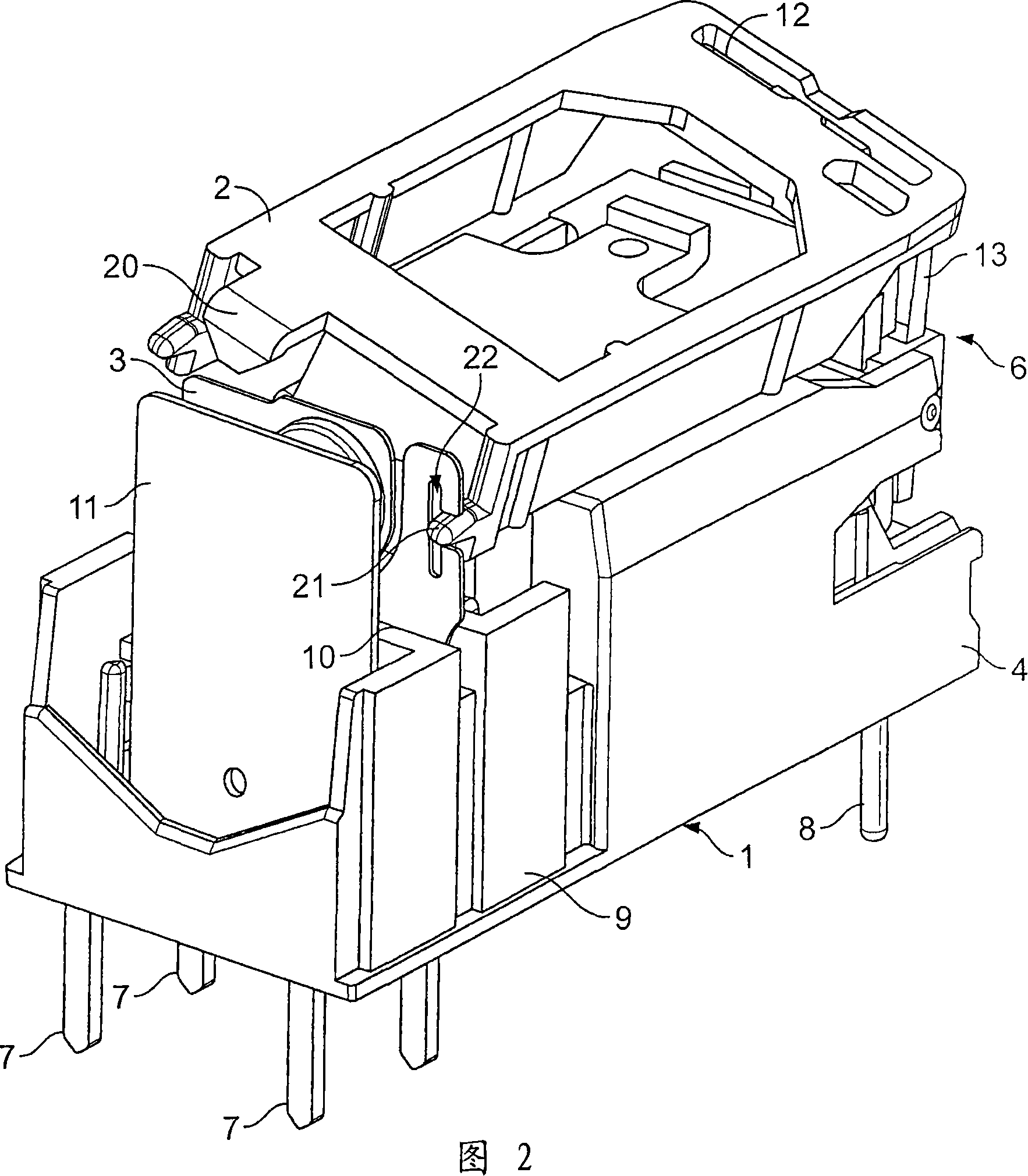
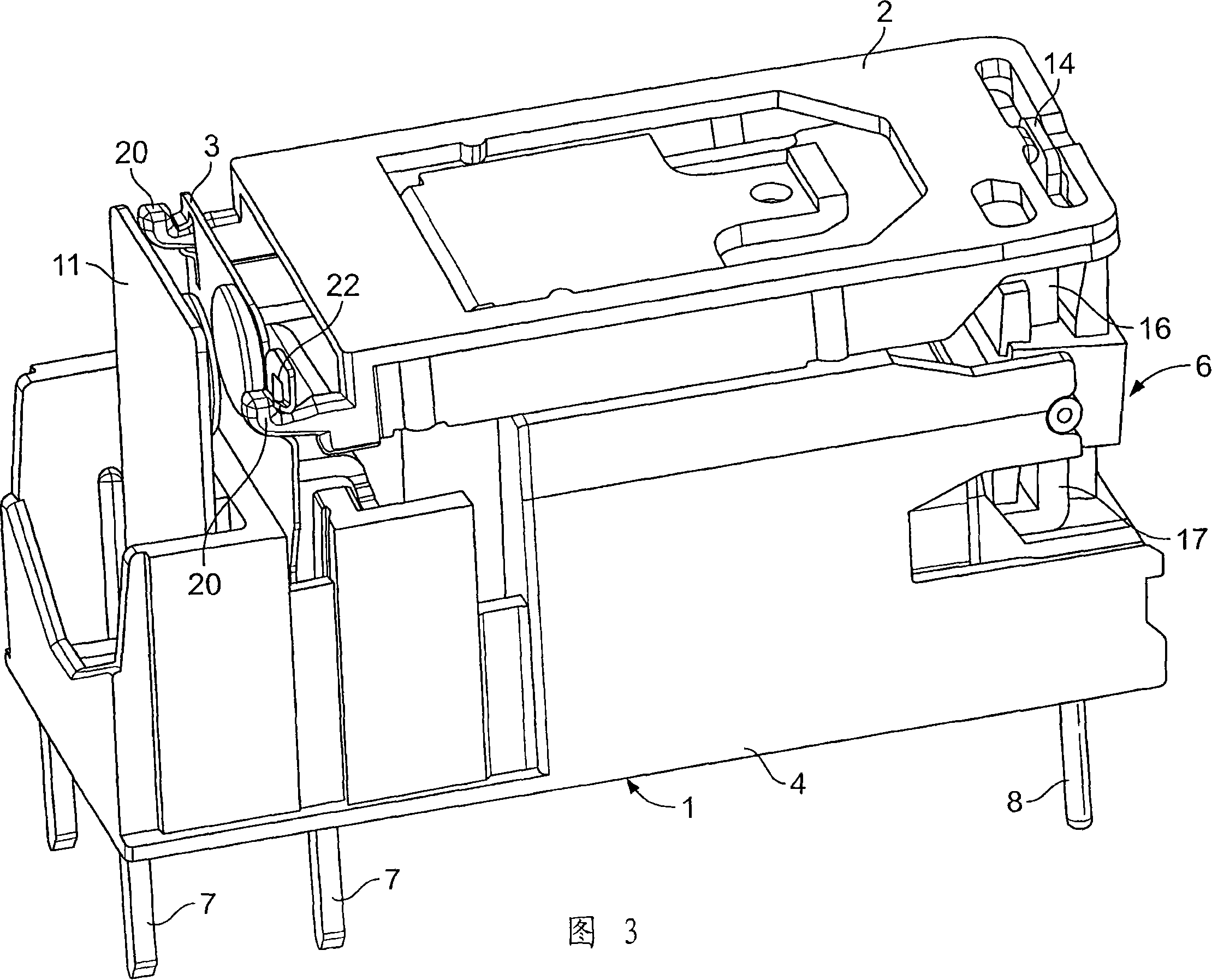
[0023] FIG. 2 shows a first embodiment of a bistable relay according to the invention with an H-shaped armature 6 . The relay shown in FIG. 2 has a base part 4 made of insulating material, extending straight towards the connection side; and a bottom side defining a bottom plane 1 from which electrical terminals 7 and 8 protrude. The base part 4 has a flat, through-bore slot for receiving the magnetic system, however, for example, the remainder comprising the raised side walls 9 and optional transverse walls 10 can be divided into separate contact carriers cabin. In the illustrated embodiment, the configuration of the relay contact system is very simple, consisting of a movable spring contact 3 and a fixed spring contact 11 . The movable spring contact 3 can be bent horizontally and moved by a comb-like slide 2 arranged parallel to the bottom plane 1 . At the end opposite to the movable spring contact 3 and the fixed spring contact 11, the slide plate 2 has an armature protru...


PUM


Abstract

An electrical relay includes a magnetic system, a contact system and a slider. The magnetic system includes an armature. The contact system includes a moveable spring contact and a fixed spring contact. The moveable spring contact is moveable between an open position and a closed position. The moveable spring contact is in electrical contact with the fixed spring contact in the closed position. The slider connects the moveable spring contact to the armature. The slider transfers movement of the armature to the moveable spring contact. The slider has at least one contact opening element extending there from. The contact opening element strikes the moveable spring contact during movement of the moveable spring contact to the open position to break any existing weld between the moveable spring contact and the fixed spring contact.

Description

technical field [0001] The invention relates to a relay having a base portion defining a base plane; a monostable and a bistable magnetic system arranged on said base portion and comprising an armature; respectively arranged perpendicularly or parallel to said base plane a movable spring contact and a fixed spring contact; the movable spring contact is arranged between the fixed spring contact and a sliding plate that can move substantially parallel or perpendicular to the bottom plane, and the movable A spring contact is movably connected to the armature by a slide acting on said movable spring contact. Background technique [0002] A (monostable) relay of this type is known, for example, from EP 1 244 127 A2 with a slide plate arranged parallel to the base plane and transmitting the movement of the armature to the contact system of the relay. In known relays, the armature engages a recess in the slide plate by means of an armature protrusion, so that the tightening or ope...

Claims


Application Information

Patent Timeline
Patent Type & Authority Applications(China)
IPC IPC(8): H01H50/64H01H50/58
CPCH01H3/001H01H50/58H01H50/642
Inventor 鲁道夫·米克尔格哈特·斯坦格尔
Owner TYCO ELECTRONICS AUSTRIA
Why Eureka
Try Eureka