Aquarium
A fish tank and bottom plate technology, applied in fish farming, application, animal husbandry, etc., can solve problems such as difficult cleaning, and achieve the effect of reducing the operating burden
- Summary
- Abstract
- Description
- Claims
- Application Information
AI Technical Summary
Problems solved by technology
Method used
Image
Examples
Embodiment 1
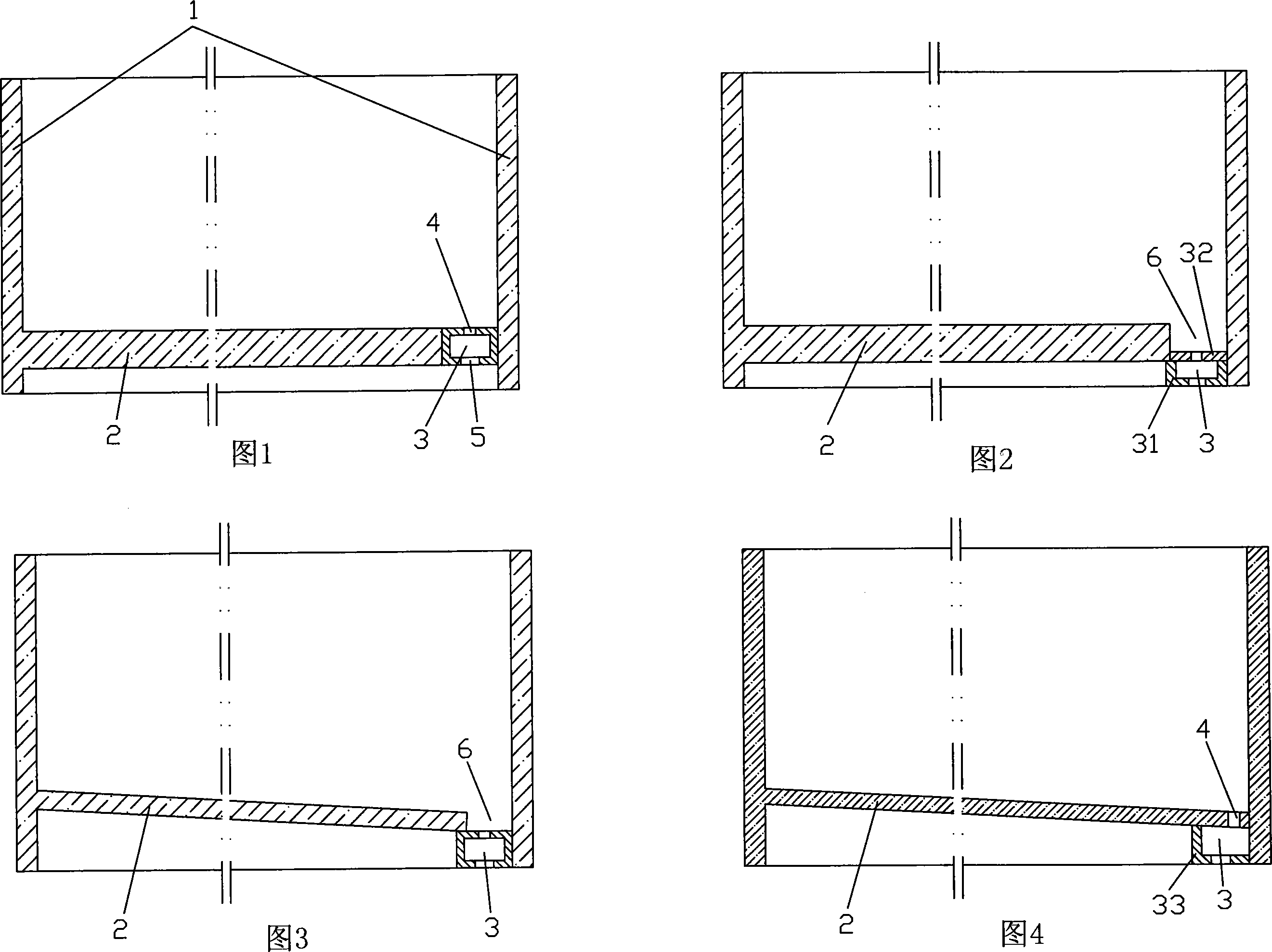
[0036] As shown in Figure 1, the fish tank includes four side walls 1 and a bottom plate 2, and the three sides of the bottom plate 2 are respectively airtightly connected with the three side walls 1 one by one, and the other side of the bottom plate 2 is connected with the adjacent side wall 1. A drainage structure 3 composed of a rectangular tube is installed in a sealed container. The rectangular tube is as long as the side of the bottom plate 2, and its two ends are respectively connected to the two side walls 1. The upper side wall of the rectangular tube is provided with a plurality of The water inlet formed by the water inlet 4 is provided with a water outlet 5 on the lower side wall of the rectangular tube.
[0037] During work, the water in the fish tank enters the inner cavity of the drainage structure 3 from the water inlet together with the fish feces and rotten leaves deposited on the bottom of the tank, and then is directly discharged from the water outlet 5, or o...
Embodiment 2
[0040] In the second embodiment shown in Figure 2, the drainage structure 3 is composed of a U-shaped groove 31 with an upward opening and a long strip cover plate 32, and the sides of the bottom plate 2 are hermetically overlapped in the U-shaped groove On the side riser, the thickness of the cover plate 32 is smaller than that of the bottom plate 2 , thus forming a groove 6 above the cover plate 32 with the same length as the side of the bottom plate 2 .
[0041] In this embodiment, by setting the groove 6, the fish feces and rotten leaves of aquatic plants deposited on the bottom of the fish tank can be well collected, thus further ensuring the effective discharge of impurities in the fish tank.
[0042] The overlapping connection form of the fish tank bottom plate 2 sides and the U-shaped groove inner side vertical plate in this embodiment can also be replaced by the butt connection mode, that is, the outer surface of the fish tank bottom plate side and the U-shaped groove ...
Embodiment 3
[0044] In the second embodiment shown in Fig. 3, the drainage structure 3 wherein still adopts the rectangular tube structure, but the airtight butt joint connection between the sides of the fish tank bottom plate 2 and the rectangular tube in Embodiment 1 is changed into an airtight lap joint connection, and Fish tank base plate 2 is inclined to be set simultaneously. Since the fish tank bottom plate 2 is overlapped with the rectangular pipe, a groove 6 is formed above the rectangular pipe.
[0045] A groove 6 with the same length is set above the drainage structure 3, and after the bottom plate 2 is inclined, impurities such as fish feces, aquatic plants and rotten leaves are automatically slid into the groove 6 along the upper surface of the bottom plate during the process of depositing to the bottom of the fish tank. , thus improving the collection effect of impurities and creating conditions for the complete removal of impurities.
PUM
 Abstract
Description
Claims
Application Information
 - R&D Engineer
- R&D Manager
- IP Professional
- Industry Leading Data Capabilities
- Powerful AI technology
- Patent DNA Extraction
Browse by: Latest US Patents, China's latest patents, Technical Efficacy Thesaurus, Application Domain, Technology Topic, Popular Technical Reports.
© 2024 PatSnap. All rights reserved.Legal|Privacy policy|Modern Slavery Act Transparency Statement|Sitemap|About US| Contact US: help@patsnap.com


