Spreader roll

A technology of spreading rollers and roller sections, applied in the field of spreading rollers, can solve problems such as damage and complex structure, and achieve the effect of not being easily soiled

Inactive Publication Date: 2007-12-12
PIKOROLLS
View PDF0 Cites 5 Cited by
  • Summary
  • Abstract
  • Description
  • Claims
  • Application Information

AI Technical Summary

Problems solved by technology

The motor requires space outside the spreader rollers, and due to the required extension shafts and connectors and other required structural components, the structure is also relatively complex and susceptible to damage

Method used


Image

  • Spreader roll
  • Spreader roll

Examples


Embodiment Construction

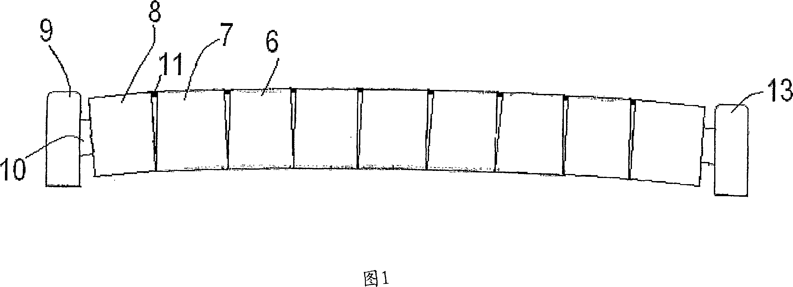
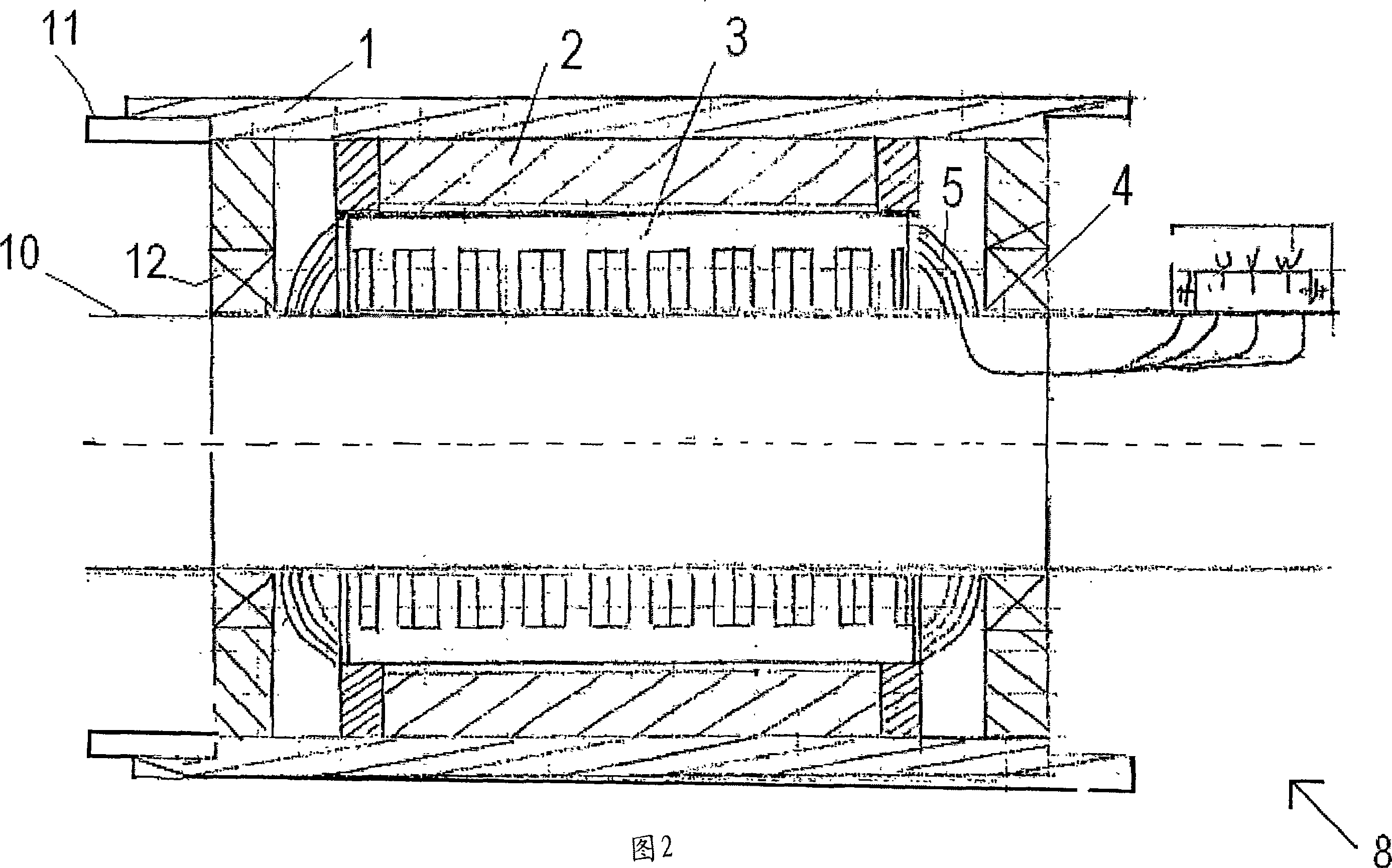
[0016] According to Fig. 1 and shown in Fig. 2, spreader roller comprises at least one actuator (actuator) and fixed stretcher roller shaft 10 that is most conducive to bending, there are roller sections 6, 7 and 8 on stretcher roller shaft 10, described The roll sections are connected to each other by flexible connector parts 11 connected to the shells 1, so that the roll section shells are fixedly supported (bearing-mounted) to rotate around the spreader roll axis, and at least one roll section 8 is an actuator, so The actuator described above is most advantageously operated as a drum motor which rotates the roll section shell 1 about the spreader roll axis.

[0017] When the roll sections 7, 8, etc. are connected to each other by flexible connector parts 11 connected to each roll section, the flexible connector parts transmit the force from each roll section to the next roll section, thus enabling all roll sections to Set 1 is able to rotate. Due to their flexibility, the ...


PUM


Abstract

A spreader roll comprising at least one actuator and a stationary and most advantageously curved spreader-roll axle (10) on which there are roll segments (6, 7 and 8) which roll segments are connected to each other with flexible connector members (11) in connection with shell sleeves (1) so that the roll-segment shell sleeves rotate bearing-mountedly around the spreader-roll axle, in which at least one roll segment (8) is an actuator which operates most advantageously as a drum motor rotating the roll-segment shell sleeves (1) around the spreader-roll axle.

Description

technical field [0001] This invention relates to spreader rolls for the paper industry. Background technique [0002] Currently, rotating mechanisms are used to rotate paper machine spreader rolls, said mechanisms being located on the outside of the spreader rolls and from which force is transmitted to the spreader rolls by means of belts, axles or other corresponding force transmission mechanisms. [0003] Said spreader rollers are known, which are rotated by using an electric motor located outside the roller near the roller, and the force to rotate the spreader roller is transmitted from the motor to the spreader roller through a belt or other corresponding force transmission member. . This arrangement has the disadvantages of great service need, wear and tear of the belts, and space requirements for equipment outside the spreader rollers. Also, contamination of the motor and belt can cause problems. [0004] Another known solution, such as the patent publication No. FI...

Claims


Application Information

Patent Timeline
Patent Type & Authority Applications(China)
IPC IPC(8): F16C13/00D21F7/02D21F1/40
CPCF16C13/003D21F7/02D21F1/40
Inventor 帕西·乌西塔洛图雷·乌西塔洛(已死亡)
Owner PIKOROLLS
Why Eureka
Try Eureka