
An eyeground observation device, an ophthalmologic image processing unit, an ophthalmologic image processing program and an ophthalmologic image processing method

一种眼底观察、图像的技术,应用在图像数据处理、眼底镜、图像增强等方向,能够解决眼底层边界的状态无法以眼睛辨视、指定困难、无法计测等问题

Inactive Publication Date: 2007-12-12
KK TOPCON
View PDF5 Cites 29 Cited by
  • Summary
  • Abstract
  • Description
  • Claims
  • Application Information

AI Technical Summary

Problems solved by technology

[0036] When a conventional optical image measuring device is used to obtain a tomographic image of the fundus, the image area directly below the fundus blood vessels (the position in the +z direction shown in FIG. The state of the layer boundary cannot be seen with the eyes
[0037] For example, as shown in FIG. 21, when the tomogram G' or layer (in the image) L1' of the fundus is taken from the fundus blood vessel (sectional image) V, due to the influence of the fundus blood vessel V, the directly below The image area V' becomes unclear, and it is impossible to grasp the state of the boundary g2' between the layer L1' and the layer L2', the state of the boundary g3' between the layer L2' and the layer L3', the state of the layer L3' and its lower layer (not shown). ) state of the boundary g4'
Therefore, the thicknesses of the layers L1', L2', L3', etc. in the forward direction of the fundus blood vessel V cannot be measured.
Therefore, the layer thickness at this position will be recorded as "0" or "unable to measure", which leads to the problem that the layer thickness of the entire acquired image cannot be measured
[0038] When the user visually recognizes the tomographic image G' to explore the image region V', it must take a considerable amount of time and labor, which is quite difficult in practical applications.
In addition, since it is difficult to analyze the tomographic image G' and specify the fundus blood vessel V, it is difficult to automatically extract the image region V' from the tomographic image G'. Generally speaking, the actual blood vessel cannot be clearly specified in this way.) In addition, the symbol LS in FIG.

Method used


Image

  • An eyeground observation device, an ophthalmologic image processing unit, an ophthalmologic image processing program and an ophthalmologic image processing method
  • An eyeground observation device, an ophthalmologic image processing unit, an ophthalmologic image processing program and an ophthalmologic image processing method
  • An eyeground observation device, an ophthalmologic image processing unit, an ophthalmologic image processing program and an ophthalmologic image processing method

Examples


Embodiment Construction

[0078] Hereinafter, a fundus observation device, an ophthalmic image processing device, an ophthalmic image processing program, and an ophthalmic image processing method according to an example of an embodiment of the present invention will be described in detail with reference to the drawings. In addition, the same reference numerals as in Fig. 19 and Fig. 20 are used for the same components as before.

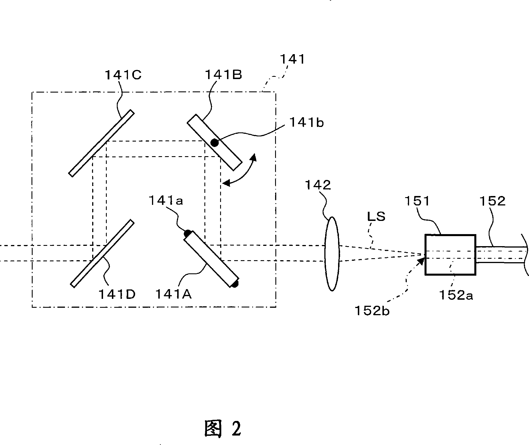
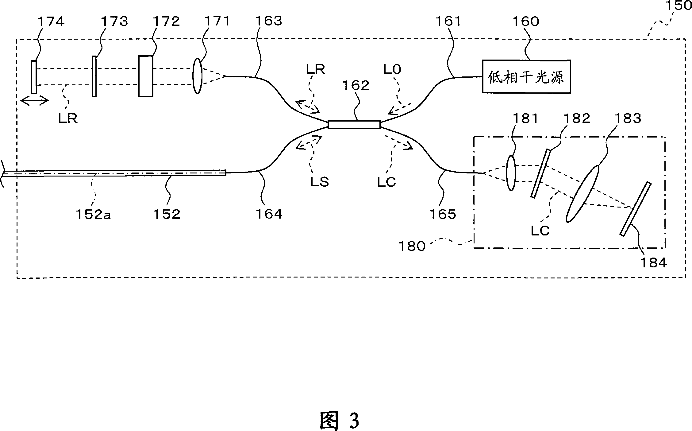
[0079] First, the configuration of the fundus observation device according to this embodiment will be described with reference to FIGS. 1 to 7 . FIG. 1 shows an example of the overall configuration of a fundus observation device 1 according to this embodiment. FIG. 2 shows the configuration of the scanning unit 141 in the fundus camera unit 1A. FIG. 3 shows the structure of the OCT unit 150 . FIG. 4 shows an example of the hardware configuration of the arithmetic control device 200 . FIG. 5 shows an example of the configuration of the control system of the fundus observati...


PUM


Abstract

First image forming part forms a two-dimensional surface image of a fundus oculi of an eye based on optically obtained data. Second image forming part forms tomographic images of fundus oculi based on data obtained by optically scanning a region of the surface of fundus oculi corresponding to at least part of two-dimensional image. Accumulated image generating part generates an accumulated image by accumulating the formed tomographic images in a depth-wise direction. Extracting part extracts first vascular territory corresponding to a fundus oculi vessel from two-dimensional image formed by first image forming part, and also extracts second vascular territory corresponding to a fundus oculi vessel from accumulated image generated by accumulated image generating part. Specification part specifies a position of a vascular cross sectional region corresponding to a cross section of a fundus oculi vessel in the tomographic image based on extracted first vascular territory and extracted second vascular territory.

Description

technical field [0001] The present invention relates to a fundus observation device, an ophthalmic image processing device, an ophthalmic image processing program, and an ophthalmic image processing method for observing the state of the fundus of an eye to be inspected. Background technique [0002] As a fundus observation device, a fundus camera has conventionally been widely used. FIG. 19 shows an example of an external structure of a conventional general fundus camera, and FIG. 20 shows an example of an optical system built therein (for example, refer to Japanese Patent Application Laid-Open No. 2004-350849). In addition, the term "observation" includes at least observation of a captured image of the fundus (in addition, observation of the fundus with the naked eye may also be included). [0003] First, the appearance structure of a conventional fundus camera 1000 will be described with reference to FIG. 19 . The fundus camera 1000 includes a gantry 3 mounted on a base ...

Claims


Application Information

Patent Timeline
Patent Type & Authority Applications(China)
IPC IPC(8): A61B3/12A61B3/18G06F17/00G06T5/00
CPCG06T2207/20136G06T2207/10101G06T2207/30041G06T7/0097G06T7/0083G06T2207/10072A61B3/102G06T7/12G06T7/174G06T7/181
Inventor 青木弘幸藤村隆福间康文塚田央木川勉
Owner KK TOPCON
Learn More