Testing fixture and machine station combination device

A technology of testing fixtures and connecting mechanisms, which is applied in the direction of electronic circuit testing, parts of electrical measuring instruments, measuring electricity, etc., can solve the problems of reducing production line efficiency, increasing testing time, and wasting time, so as to reduce assembly time, The effect of easy installation

Inactive Publication Date: 2007-11-28
JET TECHNOLOGY CO LTD
View PDF0 Cites 11 Cited by
  • Summary
  • Abstract
  • Description
  • Claims
  • Application Information

AI Technical Summary

Problems solved by technology

[0011] 1. Since the manufacturer does not only produce circuit board B for a single type of electrical product, the fixture box A1 must be designed according to the size and function of each circuit board B during testing. Therefore, each time the fixture box A1 is replaced, it must be Unplug the connection line between the connection port A12 of the fixture box A1 and the connection port A241 of the test device A24, and after replacing the fixture box A1, the connection between the connection port A12 of the fixture box A1 and the test device A24 must be reconnected. Port A241 is connected, and while repeatedly replacing the fixture box A1, it is bound to waste a lot of precious time, which will increase the test time and reduce the efficiency of the production line
[0012] 2. When replacing the fixture box A1, the fixture box A1 must be manually pushed to the test platform A2 for positioning, and when manually pushing, the fixture box A1 is not easy to accurately position on the test platform A2, then when the driver The device A23 drives the moving column A231 to move downward, and when the thimble A2321 of the pressing plate A232 is pressed against the circuit board B, the pressure on the circuit board B is uneven, and the deviation occurs during the test, which affects the test results

Method used


Image

  • Testing fixture and machine station combination device
  • Testing fixture and machine station combination device
  • Testing fixture and machine station combination device

Examples


Embodiment Construction

[0065] In order to achieve the above-mentioned purpose and effect, the technical means and structure adopted by the present invention, the features and functions of the preferred embodiments of the present invention will be described in detail as follows in order to facilitate a complete understanding.

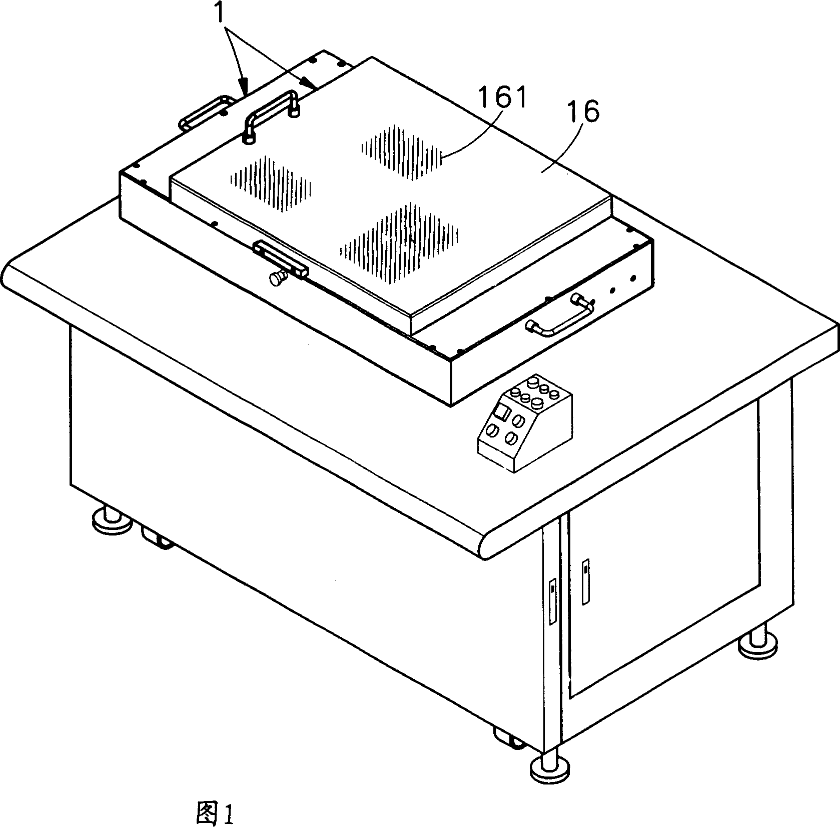
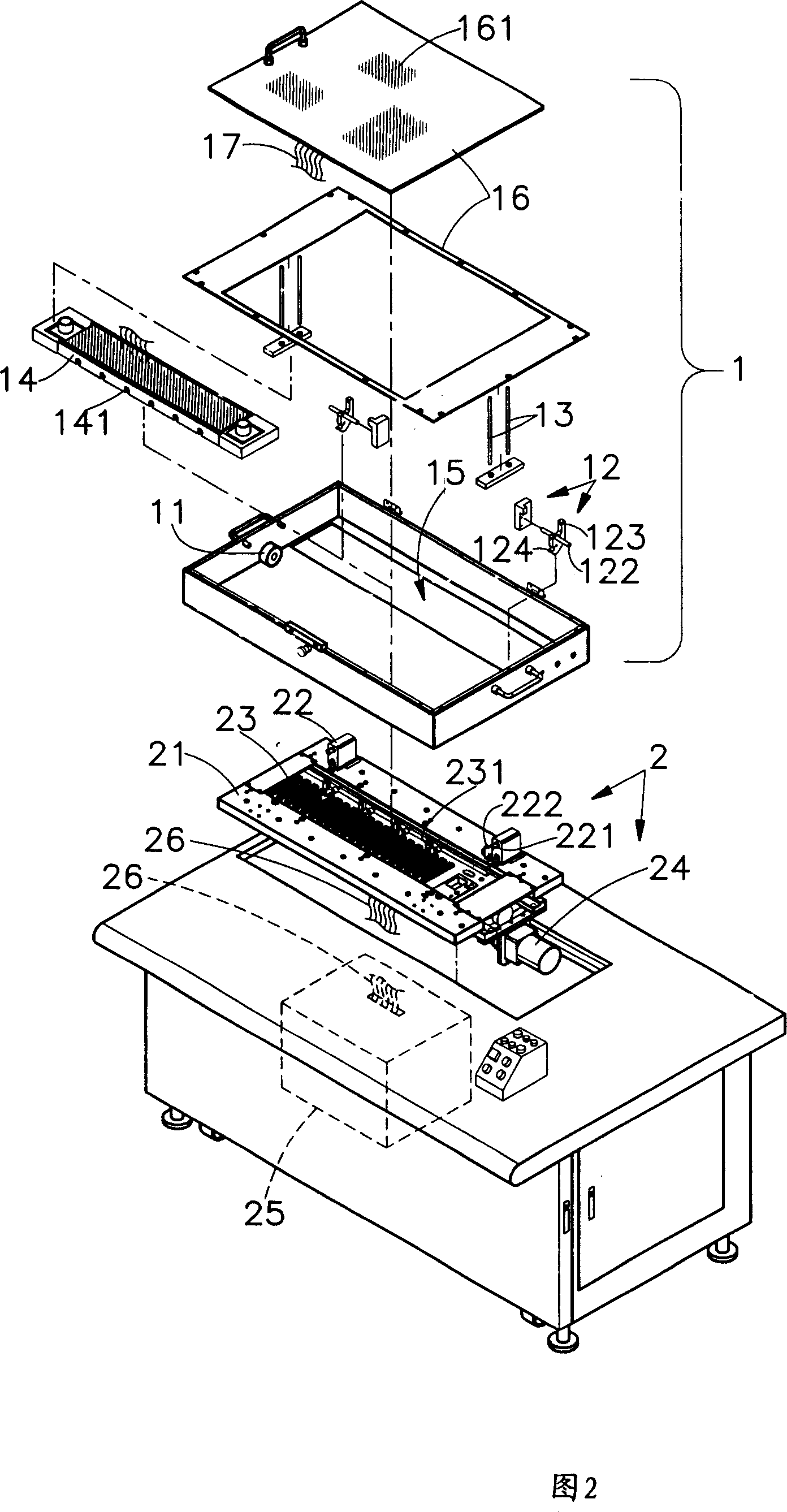
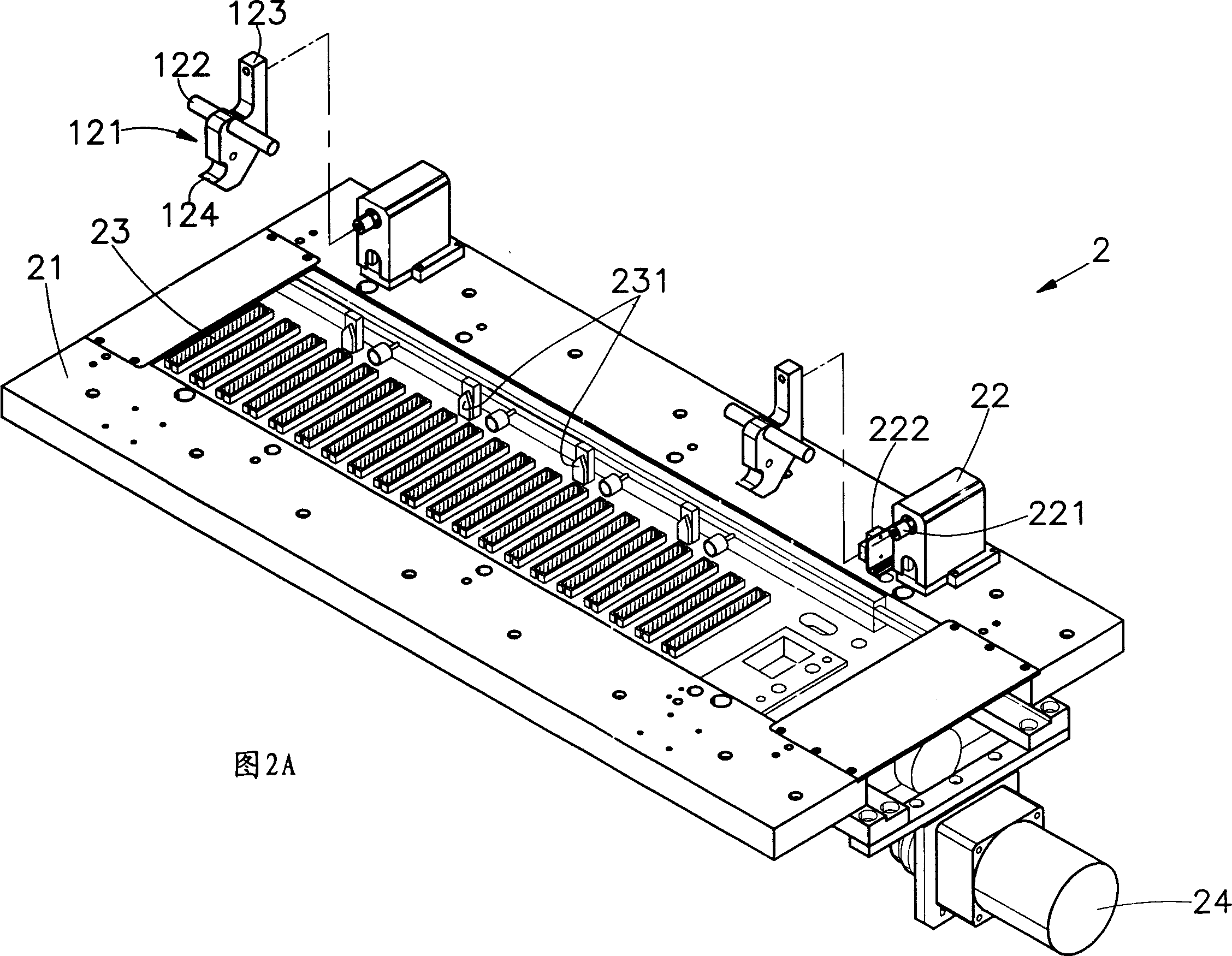
[0066] Please refer to shown in Fig. 1,2, 2A and 3, it is the three-dimensional appearance view, the three-dimensional exploded view, the partial three-dimensional appearance view and the side sectional view of the preferred embodiment of the present invention, can clearly find out the present invention from the figure It consists of a fixture box 1 and a test machine 2, wherein:

[0067] The two opposite parts of the bottom of the fixture box 1 are provided with a sliding device 11, and the sliding device 11 can be a pulley or a roller, and a clamping device 12 is pivotally arranged on two opposite wall surfaces in the fixture box 1 to hold The device 12 has a clamping compon...


PUM


Abstract

The invention relates to a connection mechanism for testing treatment tool and machine station, comprising treatment tool box, of which at the top testing circuit board can be set; and testing machine station, in which testing instrument can be set. Slipping devices are set at two facing positions at the bottom of treatment tool box so that the treatment tool box can move and locate on the bearing platform at the top of testing machine station quickly and easily. After the treatment tool box locates, there are multiple holding devices on the bearing platform to hold clamping device pivoted at two facing walls in the treatment tool box so that the clamping device can generate rotary displacement and unlocking status is formed. But the connection module can deviate from the clamping device and extend through the port at the bottom of treatment tool box. It is connected with the interlaying module set on the bearing platform in depression. Here the treatment tool box is connected with the testing machine station in current. So testing instrument in testing machine station can test the circuit board at the top of treatment tool box so that assembling time for testing circuit board is decreased greatly, it is favor of changing treatment tool boxes with different specification quickly. The invention has labor saving mechanism and so only one man is need to install easily.

Description

technical field [0001] The present invention provides a connection mechanism between a test fixture and a machine, especially a test fixture with a fixture box that can place a circuit board to be tested and a test machine with a test instrument inside, and the fixture box It can be quickly moved and positioned on the test machine. At the same time, the fixture box and the test machine are electrically connected in the form of a quick connection, which can greatly reduce the assembly time when testing the circuit board, and at the same time facilitate the rapid replacement of different specifications of the fixture. Toolbox. Background technique [0002] According to, in the current electrical products, in order to achieve easier control and reduce the production process, many manufacturers have modularized the control devices or operating devices that control the electrical products when designing electrical products, and uniformly set them in the circuit. In the board, su...

Claims


Application Information

Patent Timeline
IPC IPC(8): G01R1/02G01R31/00G01R31/28
Inventor 萧喜话刘同祥林永益
Owner JET TECHNOLOGY CO LTD
Why Eureka
Try Eureka