Improved structure of nail-slot nail-ejection of nailing machine

A nailing machine and nail groove technology, applied in nailing tools, nailing staple tools, manufacturing tools, etc., can solve the problem of hitting two T-shaped nails at the same time, and achieve the effect of improving the service life

Inactive Publication Date: 2007-11-14
APEX MFG
View PDF1 Cites 2 Cited by
  • Summary
  • Abstract
  • Description
  • Claims
  • Application Information

AI Technical Summary

Problems solved by technology

Furthermore, it is more likely to cause the disadvantage of hitting two T-shaped nails at the same time when firing

Method used


Image

  • Improved structure of nail-slot nail-ejection of nailing machine
  • Improved structure of nail-slot nail-ejection of nailing machine
  • Improved structure of nail-slot nail-ejection of nailing machine

Examples


Embodiment Construction

[0022] Regarding the technology, means and effects adopted in the present invention, a preferred embodiment is given and described in detail below with drawings, which are for illustration only, and are not limited by this structure in the patent application.

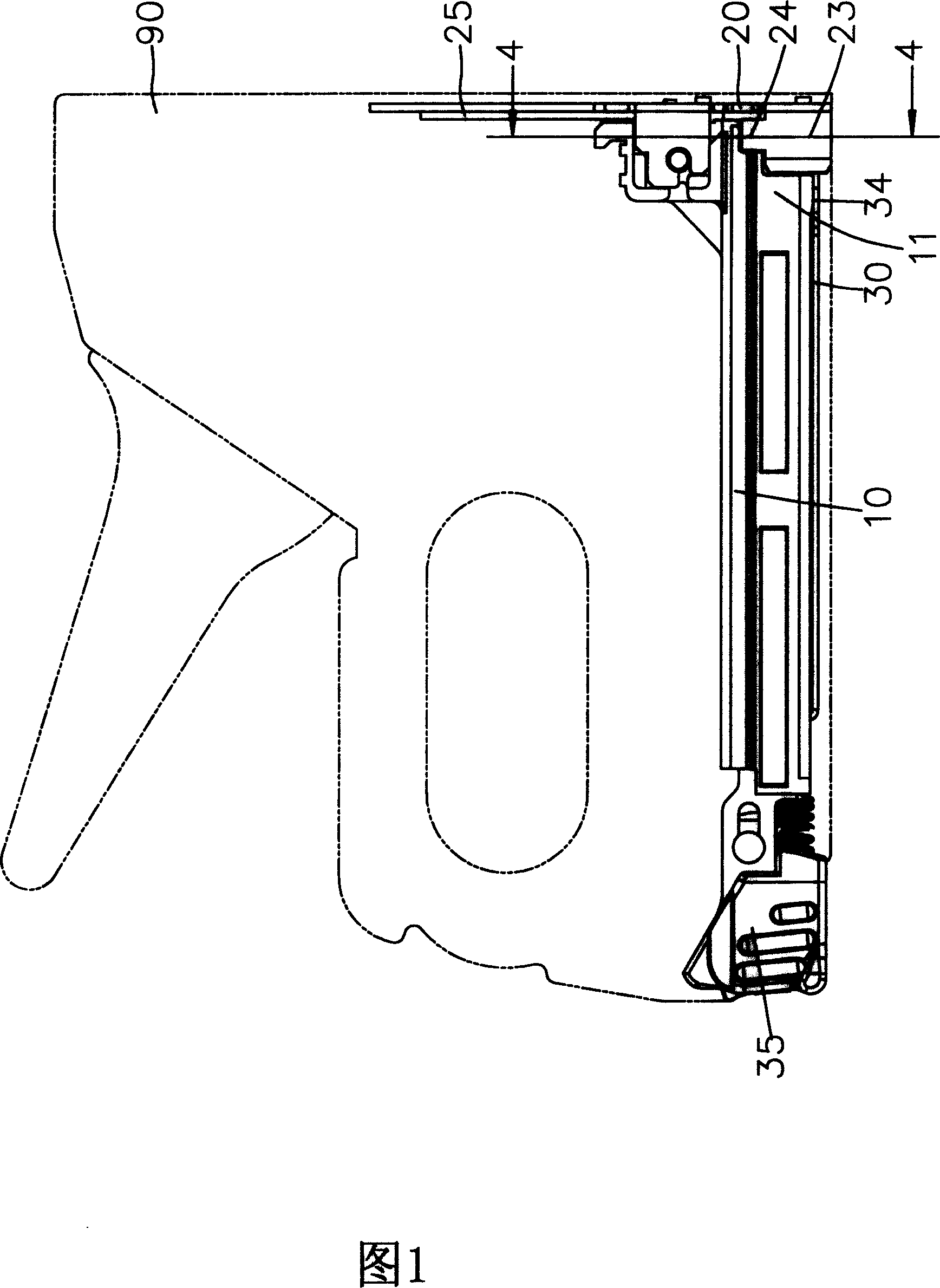
[0023] With reference to Fig. 1 and Fig. 2, the present invention comprises an outer groove seat 10 that is located on the gun body 90, a guide cover 20 that is installed on the front end of the outer groove seat 10 and an inner groove seat 30 that is located at the inside of the outer groove seat 10; The guide cover 20 is provided with a supporting end 24 to provide a good supporting effect for the T-shaped nail 91 (as shown in FIG. 6 ). in:

[0024] Please refer to Fig. 3 and Fig. 4, described outer groove seat 10 is installed on the bottom of gun body 90 (as Fig. 1), and described outer groove seat 10 is provided with two mutually parallel first side walls 11 and the second side wall 12, and a top 13 perpendicular t...


PUM


Abstract

The invention relates to an improvement of staple channel giving structure of the nail beater. It contains an external slot, a guiding cover and an inner slot. The external slot is located on the gun body and has parallel first sidewall and second sidewall, each of them has a guiding slot. The front end of the first sidewall has a gap connecting with the guiding slot. The guiding cover is equipped on the external slot and it forms a supporting end to support T staples corresponding to the gap of the first sidewall. The inner slot locates between the two sidewalls to push the T staples. Therefore, the inner slot has two guiding plates which are parallel with the two sidewalls. The baffles within one level are set on both sides of the two guiding plates. A good effect of giving staples is realized and the service life is prolonged. In addition, it avoids striking two T staples.

Description

technical field [0001] The invention relates to a nail groove structure of a nailing machine, in particular to the structure design of a guide cover, an outer groove seat and an inner groove seat to achieve a better nail output effect and prolong the service life, and avoid firing at the same time Two problems with T-shaped nails occur in the nail groove structure. Background technique [0002] Nailing machines have been used in the decoration industry for many years, and many different types of nails have emerged. Therefore, a nailing machine that can be used for many different types of nails has appeared on the market. [0003] Please refer to the "Staple and brad driving tool" patent case of US Patent No. 5967397, as shown in the appendix, its nailing machine device 10 is equipped with a nail magazine group 24 on the bottom side of the base 20 . The magazine set 24 includes a plastic magazine case 46 , a rigid magazine seat 44 , a nail pusher 48 and a spring 50 . A spac...

Claims


Application Information

Patent Timeline
Patent Type & Authority Applications(China)
IPC IPC(8): B25C1/00B25C5/16
Inventor 蔡富丞
Owner APEX MFG
Why Eureka
Try Eureka