Shaft coupling in particular for use in an electrical switch

A coupling and electric switch technology, which is applied in the field of electric switches, can solve problems such as troublesome assembly of couplings, and achieve the effect of simple structure and convenient assembly

Inactive Publication Date: 2007-10-03
SIEMENS AG
View PDF1 Cites 1 Cited by
  • Summary
  • Abstract
  • Description
  • Claims
  • Application Information

AI Technical Summary

Problems solved by technology

The disadvantage here is that the assembly of the coupling is more troublesome

Method used


Image

  • Shaft coupling in particular for use in an electrical switch
  • Shaft coupling in particular for use in an electrical switch
  • Shaft coupling in particular for use in an electrical switch

Examples


Embodiment Construction

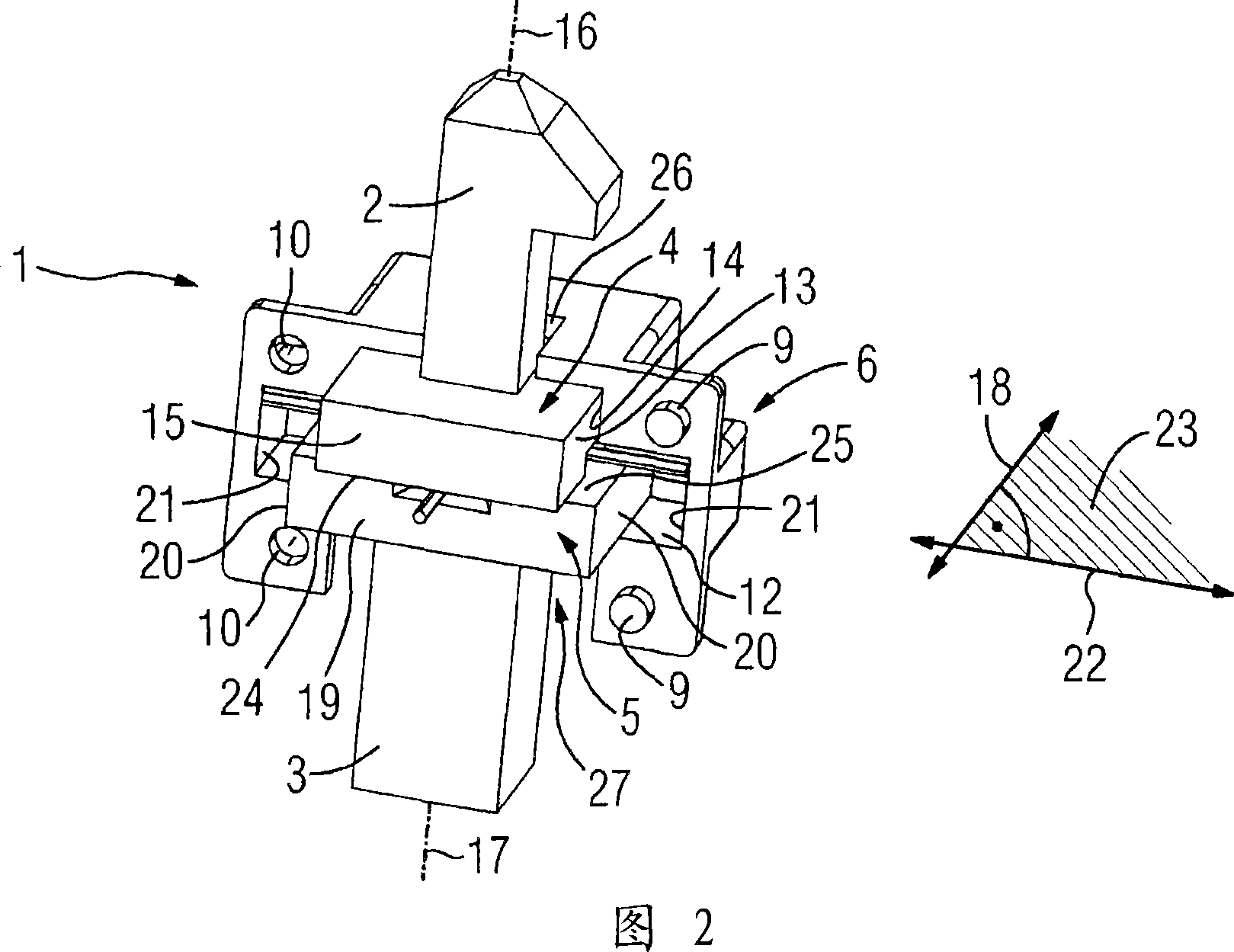
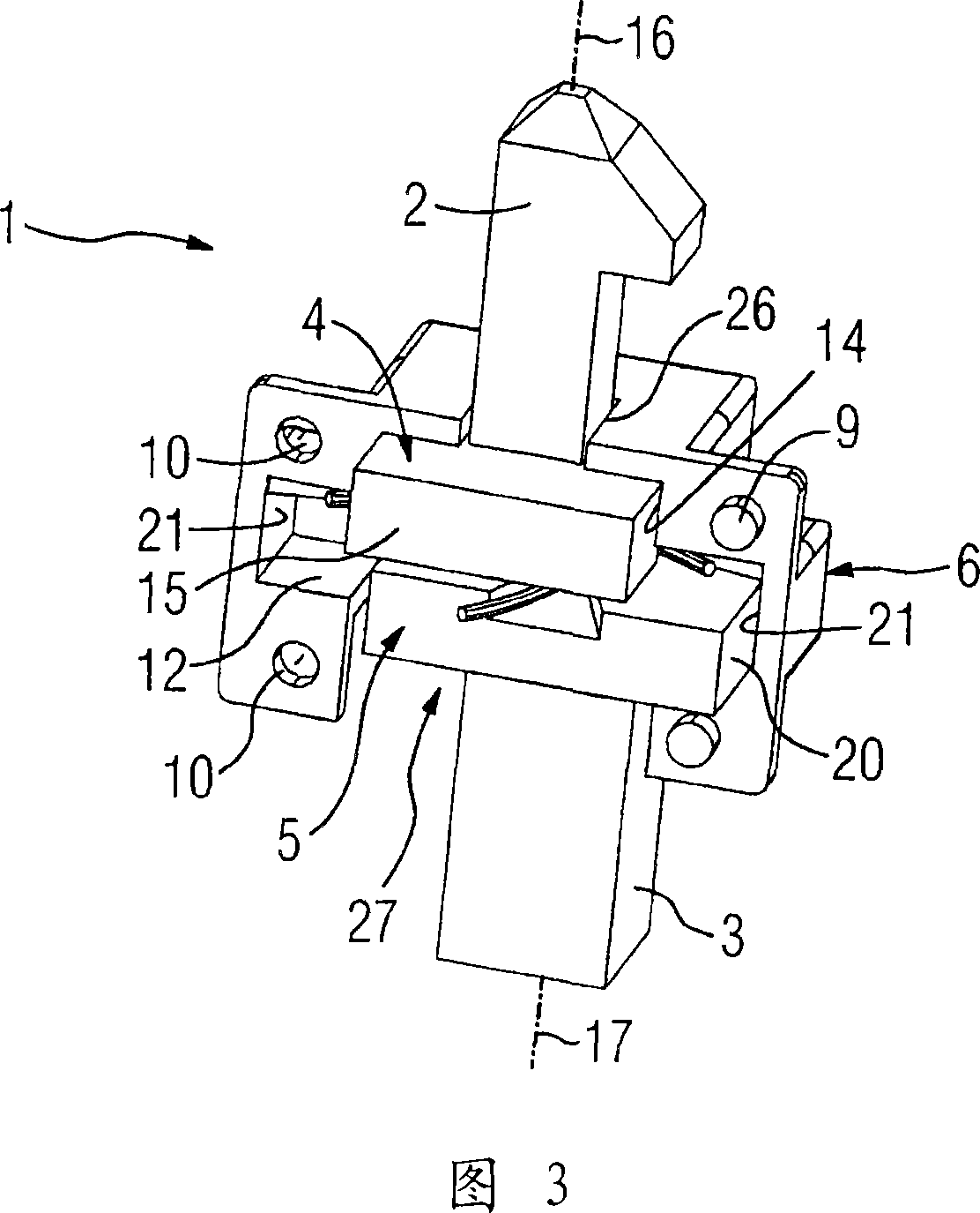
[0028] FIG. 1 shows a coupling 1 according to the invention for connecting a coupling section 2 to a shaft section 3 . The coupling section 2 is fixedly connected to a first slide 4 . The slider 4 is housed in a coupling housing 6 together with a second slider 5 which is fixedly connected to the shaft section 3 (see FIG. 2 ). Instead of a fixed connection between the slides 4 , 5 and the shaft section 3 or the coupling section 2 , any detachable connection between these components can also be used, for example a snap connection or a snap connection.

[0029] The coupling housing 6 consists of two half shells 7 , 8 which are connected to each other by four rivets 9 . The rivet 9 is pressed onto the half shells 7 , 8 , preferably made of plastic, and riveted through the hole 10 to the counterpart.

[0030] The coupling housing 6 has mounting cavities 11 , 12 arranged transversely to one another for mounting slides 4 , 5 . The cuboid-shaped first slider 4 mounted on the coupli...


PUM


Abstract

The invention relates to a shaft coupling (1) and the application of the shaft coupling (1) in an electric switch (41). Furthermore, the invention relates to an electric switch (41). In order to compensate the error between the first shaft (2) and the second shaft (3) or another component to be connected with it in a structurally simple way, a method comprising at least one corresponding to the shaft (2, 3) is proposed. The shaft coupling (1) of the slider (4, 5) provided, wherein, in order to constitute the shaft coupling of lateral movement, the slider (4) is packaged in the coupling housing (6) under the condition of designed clearance fit ), and at least one elastic element (29, 33; 37) is provided which loads the slider when the slider (4, 5) is outside its rest position.

Description

technical field [0001] The invention relates to a coupling and the application of the coupling in an electric switch. Furthermore, the invention also relates to an electric switch. Background technique [0002] When installing electrical switching devices in switching housings, housings or switching cabinets etc., dimensional deviations often occur, for example due to manufacturing tolerances or inaccuracies during installation. Especially if the switchgear is fixed, for example, on the rear wall of the switchgear and the operating handle is provided on the front wall of the switchgear designed as a door, the dimensional deviations described can lead to rotation of the actuating shaft of the switchgear and the coupling on the door Coordination between drive units is difficult or obstructed. [0003] Many solutions for compensating fit errors of this type are known from the prior art. DE 3939715 A1, for example, describes a device comprising three coupling slides which are...

Claims


Application Information

Patent Timeline
Patent Type & Authority Applications(China)
IPC IPC(8): H01H3/10F16D3/06F16D3/04
CPCH01H3/10H01H2003/105
Inventor 曼弗雷德·克罗内斯于尔根·库默
Owner SIEMENS AG
Why Eureka
Try Eureka