
Knock sensor

A technology of deflagration sensor and piezoelectric element, which is applied in the field of deflagration sensor, can solve the problems of wrong judgment of deflagration signal and superimposition, and achieve the effect of changing output sensitivity and stabilizing output

Inactive Publication Date: 2007-10-03
MITSUBISHI ELECTRIC CORP
View PDF1 Cites 3 Cited by
  • Summary
  • Abstract
  • Description
  • Claims
  • Application Information

AI Technical Summary

Problems solved by technology

Thus, in the structure of the knock sensor in the past, there was such a problem that when the electrode layer of the annular piezoelectric element was partially formed, noise caused by temperature change would be superimposed on the output signal, and in the ECU Will misjudge the deflagration signal

Method used


Image

  • Knock sensor
  • Knock sensor
  • Knock sensor

Examples


Embodiment Construction

[0040] Embodiment 1

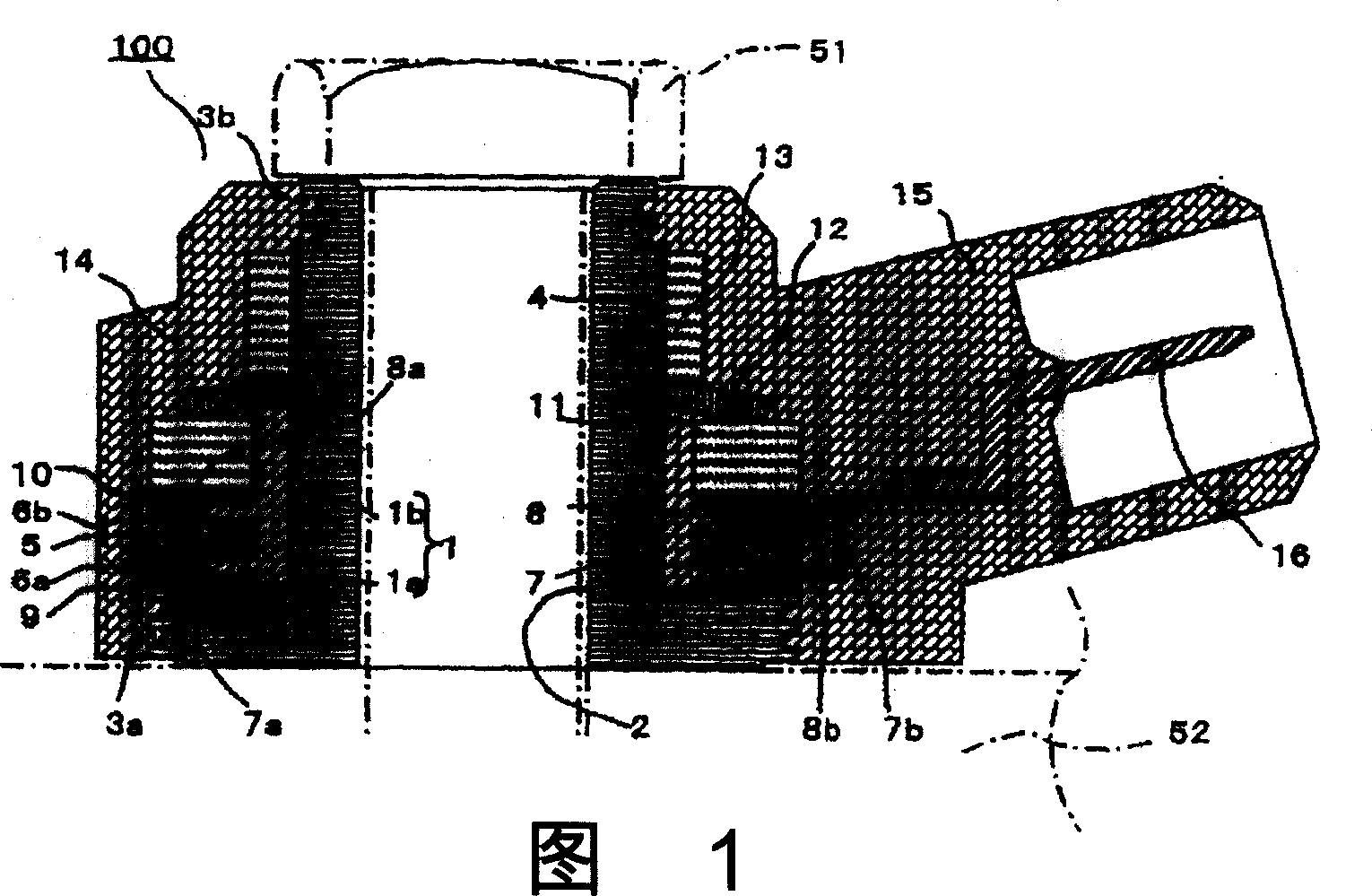
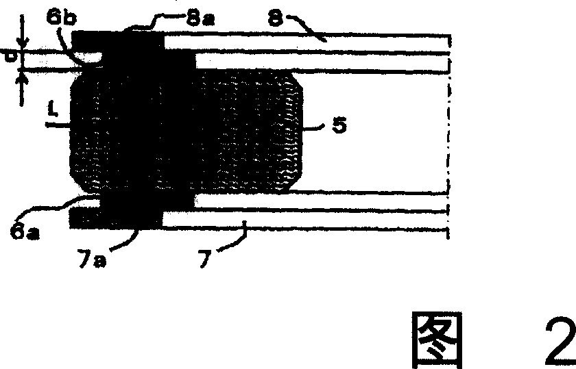
[0041] Fig. 1 is a longitudinal sectional view of a knock sensor according to Embodiment 1 of the present invention, and Fig. 2 is an enlarged sectional view illustrating a main part of the knock sensor according to Embodiment 1 of the present invention.

[0042] In Fig. 1 and Fig. 2, the base 1 is made of metal materials such as SWCH (steel for cold rolling), and has an annular flange portion 1a and a cylindrical portion 1b extending axially from the flange portion 1a. A through hole 2 is formed axially through the flange portion 1a and the cylindrical portion 1b. Then, a plurality of engagement grooves 3a, 3b are respectively formed on the outer peripheral surface of the flange portion 1a and the outer peripheral surface of the front end portion of the cylindrical portion 1b. Furthermore, the male screw portion 4 is engraved on a predetermined area of ​​the front end side outer peripheral surface of the cylindrical portion 1b.

[0043] The piezoelectr...


PUM


Abstract

To provide a knock sensor achieving a sensor structure capable of changing output sensitivity without changing a sensor outer shape and suppressing the occurrence of noise associated with temperature variation. A laminate comprising a first insulating sheet 9, a first terminal plate 7, a piezoelectric element 5, a second terminal plate 8, a second insulating sheet 10, a weight 11, and a disk spring 12 is externally fitted into a cylindrical part 1b of a base 1, nipped, pressed, and held between a nut 13 and a flange part 1a of the base 1, and resin molded. Annular partial electrodes 6a, 6b having a width narrower than a radial direction width of the piezoelectric element 5 are formed on both front and back surfaces of the piezoelectric element 5, and the partial electrodes 6a, 6b are formed so that a relationship of L / d<80 is satisfied between a radial direction interval L of an outer circumferential edge part electrode non-formation area and an electrode film thickness d.

Description

technical field [0001] The invention relates to a non-resonance type deflagration sensor, which is installed on an internal combustion engine through bolts. If the internal combustion engine generates deflagration vibration, the vibration is converted into a voltage signal by a piezoelectric element clamped inside. And the voltage signal is used as an output signal, and then output to the outside. Background technique [0002] A conventional knock sensor has a cylindrical portion and a flange portion formed on the lower portion of the cylindrical portion, and the screw has a metal sleeve formed on the upper outer peripheral surface of the cylindrical portion. Then, the first ring-shaped electrode plate is fitted on the cylindrical part through the insulating plate so that it is located on the flange part, and the ring-shaped piezoelectric element is fitted on the cylindrical part so that it is located on the first ring-shaped electrode. On the plate, the second annular elec...

Claims


Application Information

Patent Timeline
Patent Type & Authority Applications(China)
IPC IPC(8): G01L23/22G01H11/08G01M15/04G01M15/12F02D35/00H10N30/30G01H17/00
CPCG01L23/222G01L23/22G01H17/00
Inventor 佐藤宗一柴田治昌横井章人谷本考司
Owner MITSUBISHI ELECTRIC CORP
Learn More