Broadcast processing method for network system and network system
一种网络系统、处理方法的技术,应用在广播处理方法及该网络系统领域,能够解决难以减少广播处理时间、广播处理时间限制等问题,达到减少传送处理时间、高速传送处理的效果
- Summary
- Abstract
- Description
- Claims
- Application Information
AI Technical Summary
Problems solved by technology
Method used
Image

Examples
no. 1 example
[0052] Fig. 5 is a schematic diagram showing the first embodiment of the broadcast processing of the present invention, Fig. 6 is a schematic diagram showing the data stream broadcast in Fig. 5, Fig. 7 is a flow chart showing the processing of the data transmission source node in Fig. 5, and Fig. 8 is a flowchart showing the processing of the data receiving source node.
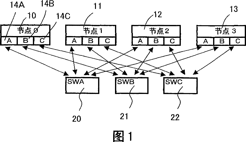
[0053] As shown in FIG. 5, node 10 divides a transmission block and transmits the divided transmission block to each node 11, 12, and 13 via individual network adapters 14A, 14B, and 14C, as indicated by (1). Then, each node 11, 12, and 13 that has received the data transmits the received divided data to a plurality of nodes that have not received the divided data, as indicated by (2).
[0054] Such data transfer is described with reference to FIG. 6 using an example of transferring the same data transfer amount as in FIGS. 13 and 14 . In other words, an example will be described when the node 10 broadcasts ...
no. 2 example
[0076] FIG. 9 is a diagram showing broadcast processing according to a second embodiment of the present invention.
[0077] In this embodiment, broadcast processing is performed at a higher speed by overlapping two data transfers in the first embodiment. FIG. 9 is an example when the node 10 broadcasts 10 blocks D0 to D9 of data to the other three nodes 11 , 12 and 13 .
[0078] First, the node 10 divides the data to be broadcast into 10 blocks, D0 to D9. Each block of data D0 , D3 and D6 is transferred from each network adapter 14A, 14B and 14C of node 10 to the corresponding network adapter 14A, 14B and 14C of nodes 11 , 12 and 13 .
[0079] In a second transfer, each block of data D1 , D4 and D7 is transferred from each network adapter 14A, 14B and 14C of node 10 to the corresponding network adapter 14A, 14B and 14C of nodes 11 , 12 and 13 .
[0080] Simultaneously, the node 11 that has received a data block D0 transfers the received data block D0 from both network adapte...
no. 3 example
[0094] Fig. 10 is a diagram showing broadcast processing according to a third embodiment of the present invention. In this embodiment, data is broadcast from node 0 to nodes 1 to 15 in a network system of 16 nodes including nodes 0 to 15, each of which has three network adapters.
[0095] First, node 0 divides 12 data blocks D0 to D11 into four in the same manner as in the first embodiment in which four nodes 0, 4, 8, and 12 are target nodes. Each network adapter 14A, 14B, and 14C of node 0 transmits each of the three data blocks D0-D2, D3-D5, and D6-D8 to the corresponding network adapter 14A, 14B, and 14C of nodes 4, 8, and 12.
[0096] Then, the second data transfer starts, wherein the node 4 that has received the three data blocks D0 to D2 transfers the received three data blocks D0 to D2 from the two network adapters 14A and 14B to the node 4 that has not received the data D0 to D2 Network adapters 14A and 14B of nodes 8 and 12 .
[0097] In the same way, the node 8 tha...
PUM
 Abstract
Description
Claims
Application Information
 - R&D
- Intellectual Property
- Life Sciences
- Materials
- Tech Scout
- Unparalleled Data Quality
- Higher Quality Content
- 60% Fewer Hallucinations
Browse by: Latest US Patents, China's latest patents, Technical Efficacy Thesaurus, Application Domain, Technology Topic, Popular Technical Reports.
© 2025 PatSnap. All rights reserved.Legal|Privacy policy|Modern Slavery Act Transparency Statement|Sitemap|About US| Contact US: help@patsnap.com