
Peer-to-peer video monitoring method based on the Internet

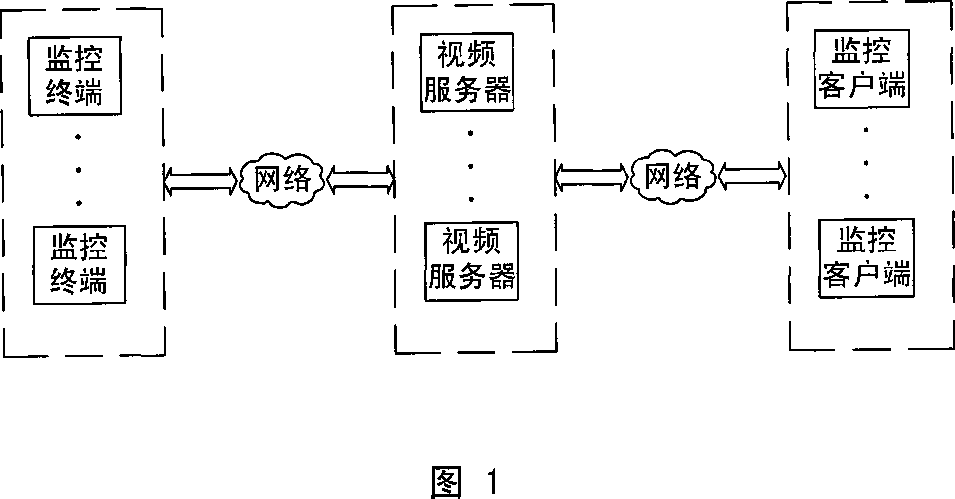
An Internet and video surveillance technology, applied in closed-circuit television systems, electrical components, transmission systems, etc., can solve problems such as limited application scale, difficult deployment, and heavy load, and achieve data security, easy deployment, and cost reduction.

Inactive Publication Date: 2007-09-12
太仓尚善科创发展有限公司
View PDF0 Cites 31 Cited by
  • Summary
  • Abstract
  • Description
  • Claims
  • Application Information

AI Technical Summary

Benefits of technology

This patented technology helps prevent unauthorized access on networks while ensuring security measures such as logging into servers at specified times. It also allows customers to verify who's watch what happens when accessing them remotely instead of relying solely upon central control systems. Additionally, this technology conserves resources because all necessary connections require minimal effort. Overall, these improvements improve efficiency, reliability, safety, privacy, and usableness (UX) capabilities across different types of environments like internet cafés where multiple clients may want to join).

Problems solved by technology

This patented describes two main limitations associated with conventional internet web camera systems - they have issues like severe loading due to their own weight and expensive equipment needed. Additionally, these cameras require an external connection to access them, which limits its usages when trying to monitor larger areas without having to connect directly into the same local area servicing stations. There is currently no solution available at present because of lack of suitable infrastructure support.

Method used


Image

  • Peer-to-peer video monitoring method based on the Internet
  • Peer-to-peer video monitoring method based on the Internet
  • Peer-to-peer video monitoring method based on the Internet

Examples


Embodiment

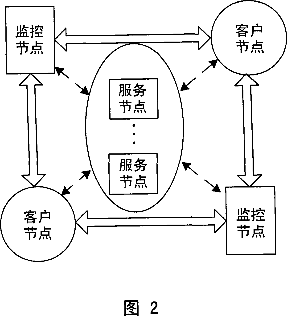
[0070] Embodiment: Fig. 2 is the peer-to-peer video surveillance network topological structure diagram based on Internet of the present invention, this peer-to-peer video surveillance network based on Internet is made up of these three types of nodes of monitoring node, client node, service node, service There is at least one node, several monitoring nodes and customer nodes, and the three types of nodes are connected to each other through the Internet. The Internet adopts the TCP / IP protocol, and the protocol version is IPV4.

[0071] 1. The three types of nodes are described as follows:

[0072] 1. Monitoring node

[0073] The monitoring node is a network device with video function, which is composed of a computer (or an embedded system device) and one or more video source devices (such as cameras).

[0074] The monitoring node tasks are mainly:

[0075] (1) Log in to the video surveillance system;

[0076] (2), collect video signal and digitize it;

[0077] (3) Compress...


PUM


Abstract

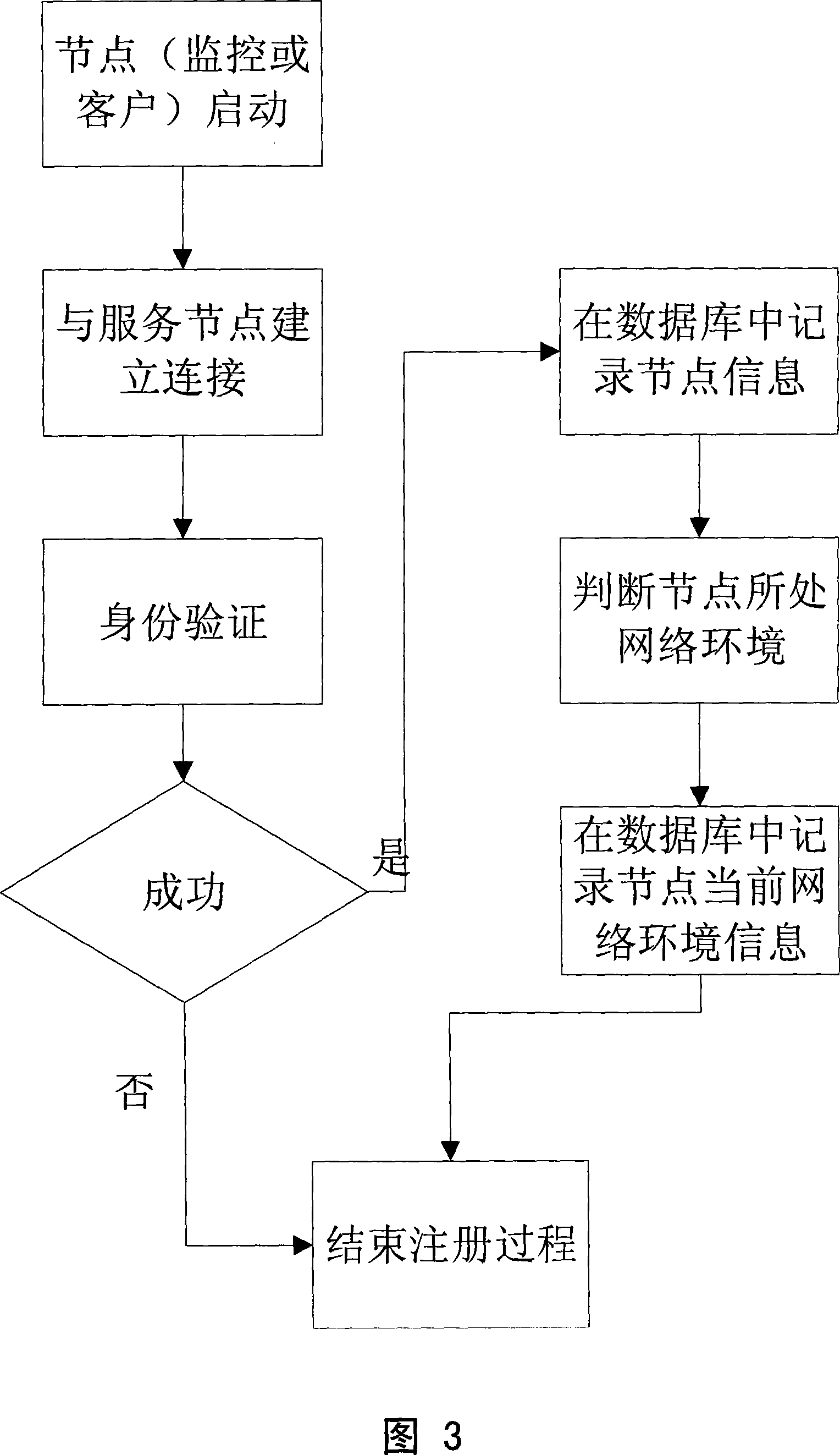
Based on the Internet, such as video surveillance methods, the monitoring nodes, the nodes customer service nodes of these three types of nodes based on the existing Internet component video surveillance network, which is a joint monitoring with the video network devices, the digital video signal compression and coding, through the Internet and video data will be sent directly to customers node; customers nodes is a function of a network terminal equipment, directly through network access control node from the video surveillance data show that after the video decoder; service node is a public IP address with the network equipment to assist customers nodes and monitoring network nodes to establish direct links, so as to achieve control nodes directly with the client node data exchange. This invention does away with the existing network video monitoring system in the video server performance bottlenecks, a client node and control nodes, and so on (peer to peer) direct data exchange program, which completely resolve the existing video surveillance technology can not solve the contradiction.

Description


Claims


Application Information

Patent Timeline
Owner 太仓尚善科创发展有限公司
Learn More