
Non negative torque outer-rotor permanent magnet motor

A permanent magnet motor and negative torque technology, which is applied in the direction of motors, electric vehicles, electrical components, etc., can solve the problems of heavy load, increased power output, and high cost

Inactive Publication Date: 2007-08-29
阮桂林
View PDF0 Cites 2 Cited by
  • Summary
  • Abstract
  • Description
  • Claims
  • Application Information

AI Technical Summary

Problems solved by technology

[0002] At present, energy and environmental protection have been the most concerned issues of people. Electric vehicles, electric motorcycles, and electric bicycles have been widely developed and used because of the advantages of tailless steam, safety, and energy saving. However, they require large-capacity livestock batteries and are expensive. The distance of a single electric drive is limited and is restricted. How to reduce the negative torque of the permanent magnet motor, improve the effect of the permanent magnet energy, and increase the power output are problems that are tried to be solved in the design of this field.
Our country is rich in magnetic mineral resources, research and development of the utilization of magnetic energy, design and manufacture of non-negative torque external rotor permanent magnet motors, and convert more magnetic energy into mechanical energy is a difficult problem for human research. Related permanent magnet motors have been retrieved and published or authorized , there is a negative torque problem in the rotation process, the load is large, and the power consumption is large, which cannot meet the ideal requirements of practical applications.

Method used


Image

  • Non negative torque outer-rotor permanent magnet motor
  • Non negative torque outer-rotor permanent magnet motor
  • Non negative torque outer-rotor permanent magnet motor

Examples


Embodiment Construction

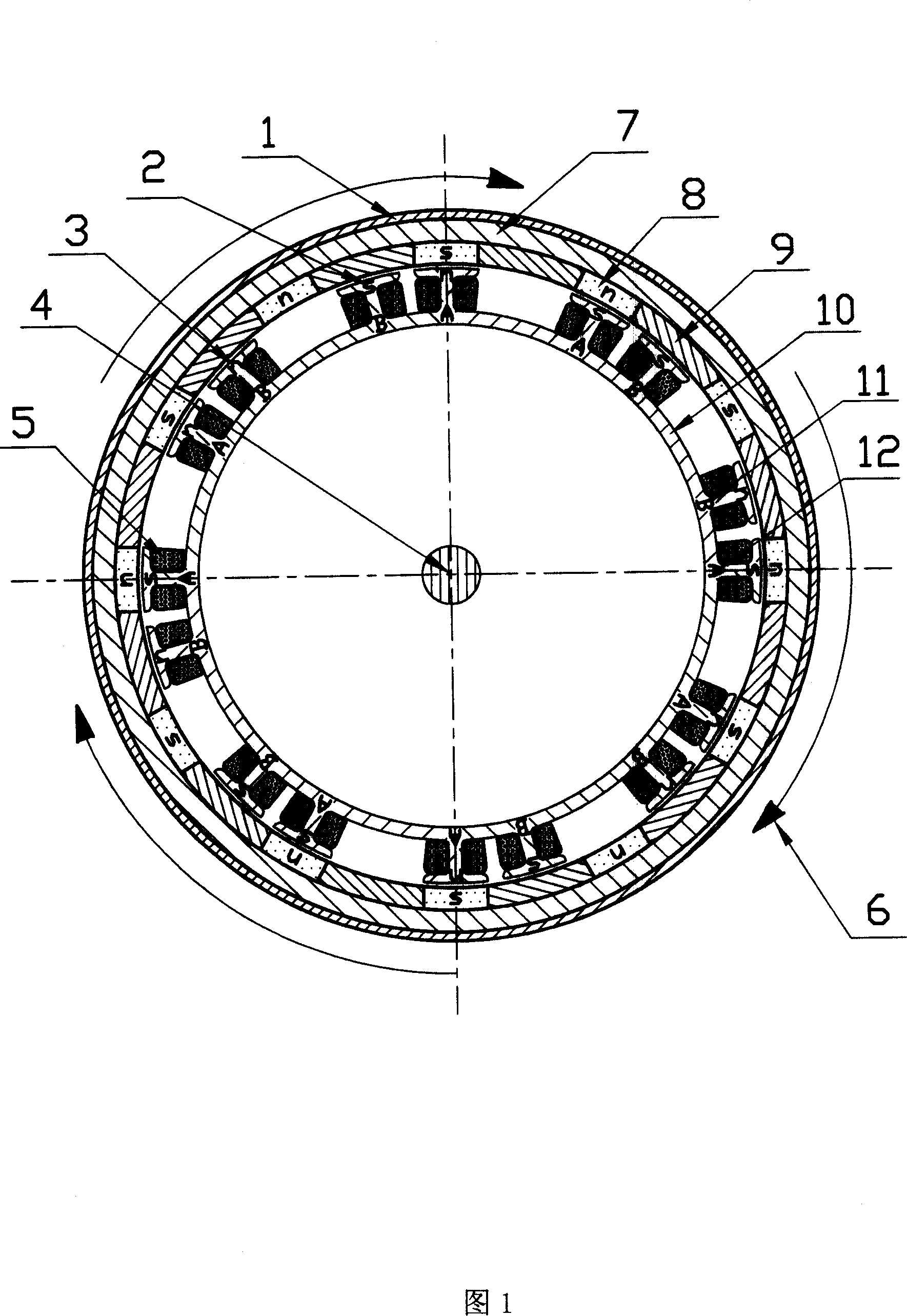
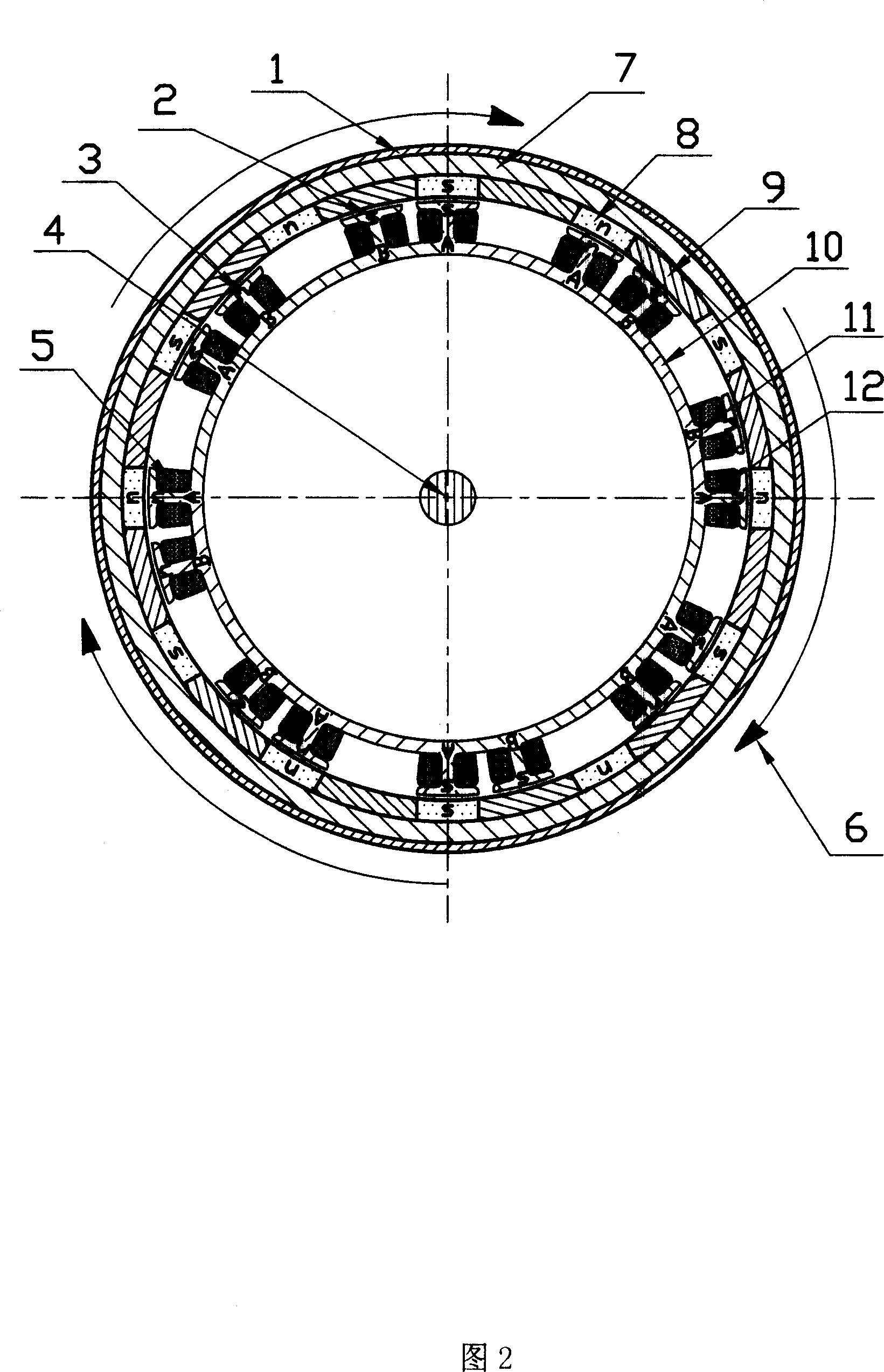
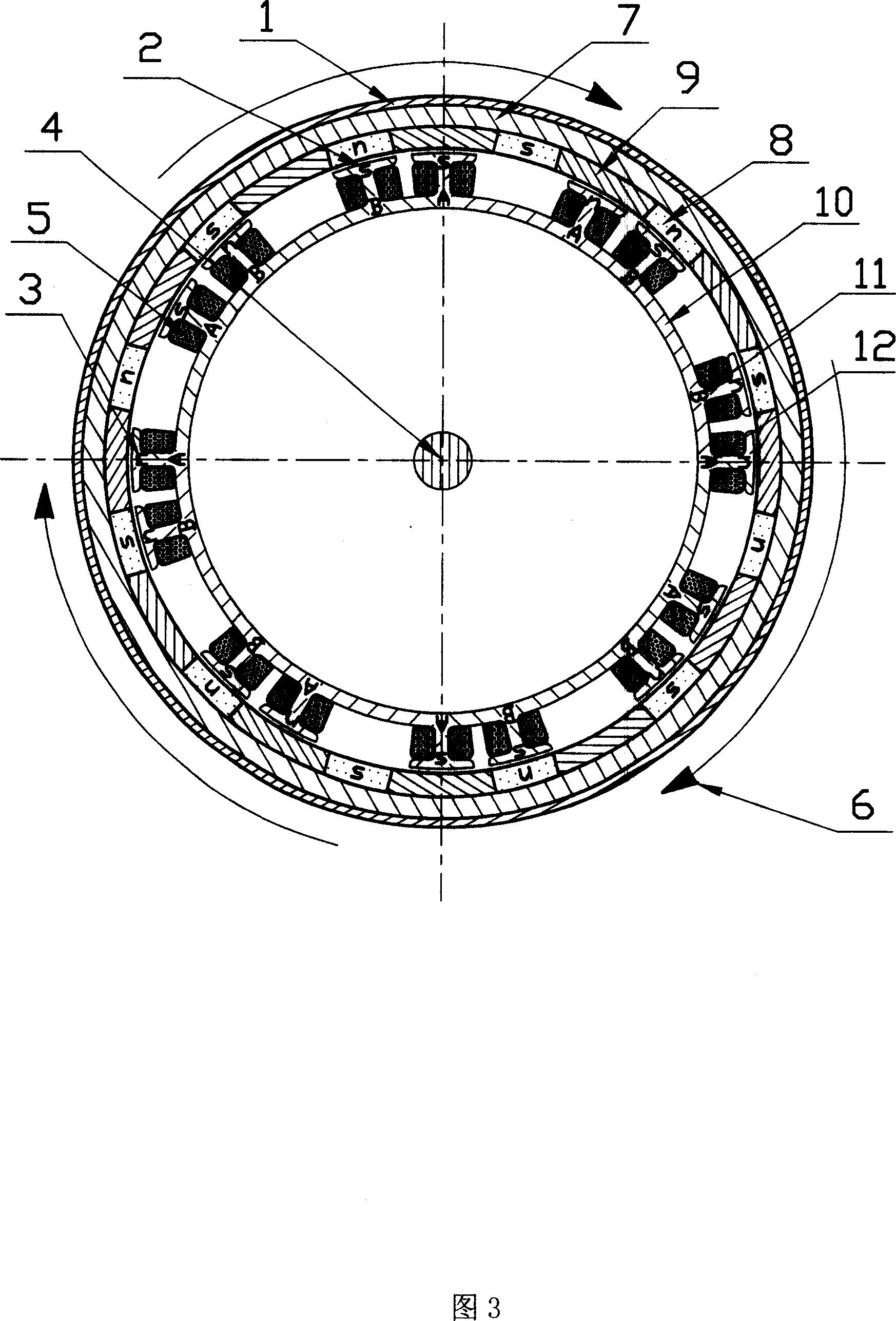
[0009] Explain in conjunction with the accompanying drawings; according to the drawings: the rotor casing (1), the rotor magnetizer (7), the magnetic isolation block (9), the rotor permanent magnet (8), plus the bearing and the cover plate to form a rotor; the stator A magnetizer (10), a coil winding (5), a central shaft (4) and a cover plate form a stator; and a current commutator is added to form a motor.

[0010] Refer to the drawings for display; on the stator (11) represents the coil winding of group B, (12) represents the coil winding of group A, (2) represents the S pole of the transformed magnetic field, (3) represents the N pole of the transformed magnetic field, and (6) represents the direction of rotation .

[0011] The invention determines the rotation direction of the rotor according to the direction of the initial input current. According to Fig. 1, the coil winding (5) of group A (12) is consistent with the rotor permanent magnet (8) and the central axis (4) ce...


PUM


Abstract

Comparing with same kind of electrical motor, the disclosed permanent magnet motor uses less conduction wire, magnet material, and permanent magnetic material. The disclosed permanent magnet motor possesses features of low cost, high magnetic energy transform, small starting up current, no negative moment, powerful torsion, small power consumption. The motor is applicable to electric automobile, and other dynamical power.

Description

technical field [0001] The invention relates to a permanent magnet motor, in particular to the design of a novel non-negative torque outer rotor permanent magnet motor. Background technique [0002] At present, energy and environmental protection have been the most concerned issues of people. Electric vehicles, electric motorcycles, and electric bicycles have been widely developed and used because of the advantages of tailless steam, safety, and energy saving. However, they require large-capacity livestock batteries and are expensive. The distance of a single electric drive is limited and restricted. How to reduce the negative torque of the permanent magnet motor, improve the effect of the permanent magnet energy, and increase the power output are problems to be solved in the design of this field. Our country is rich in magnetic mineral resources, research and development of the utilization of magnetic energy, design and manufacture of non-negative torque external rotor perm...

Claims


Application Information

Patent Timeline
IPC IPC(8): H02K23/04H02K23/26H02K23/36
CPCY02T10/641Y02T10/64
Inventor 阮桂林阮仁燕
Owner 阮桂林
Learn More