Turbine grinder

A pulverizer, turbine technology, used in grain processing and other directions

Inactive Publication Date: 2007-08-08
凌渊明
View PDF0 Cites 3 Cited by
  • Summary
  • Abstract
  • Description
  • Claims
  • Application Information

AI Technical Summary

Problems solved by technology

[0002] Existing pulverizer 1 structure is as shown in Fig. 1~Fig. It is assumed that the shaft rod 13 penetrates through several turntables 14 and is consolidated with them. The turntable 14 is provided with a number of distribution plates 15 and blades 16. The input raw materials are stirred by the distribution plates 15 and crushed by the blades 16. The raw material continues to be pulverized along the pulverizing chamber 12 to the next rotary disc 14 through the principle of centrifugal force; however, the pulverizing chamber 12 of the existing pulverizer 1 is designed to be cylindrical, and each rotary disc 14 has an equal outer diameter, so pulverizing The final raw materials often go to the outlet 11 before entering the second, third, and fourth turntables 14, so the crushing rate of the raw materials is 25 to 30% (the particle size of 0.42mm can be reused after crushing), and the rest of the raw materials It must be sent to the crushing chamber 12 from the entrance 10 again for crushing operation

Method used


Image

  • Turbine grinder
  • Turbine grinder
  • Turbine grinder

Examples


Embodiment Construction

[0013] Relevant present invention is for reaching above-mentioned purpose of use and effect, the technical means that adopts, presents preferred feasible embodiment, and cooperates as shown in the drawing, is described in detail as follows:

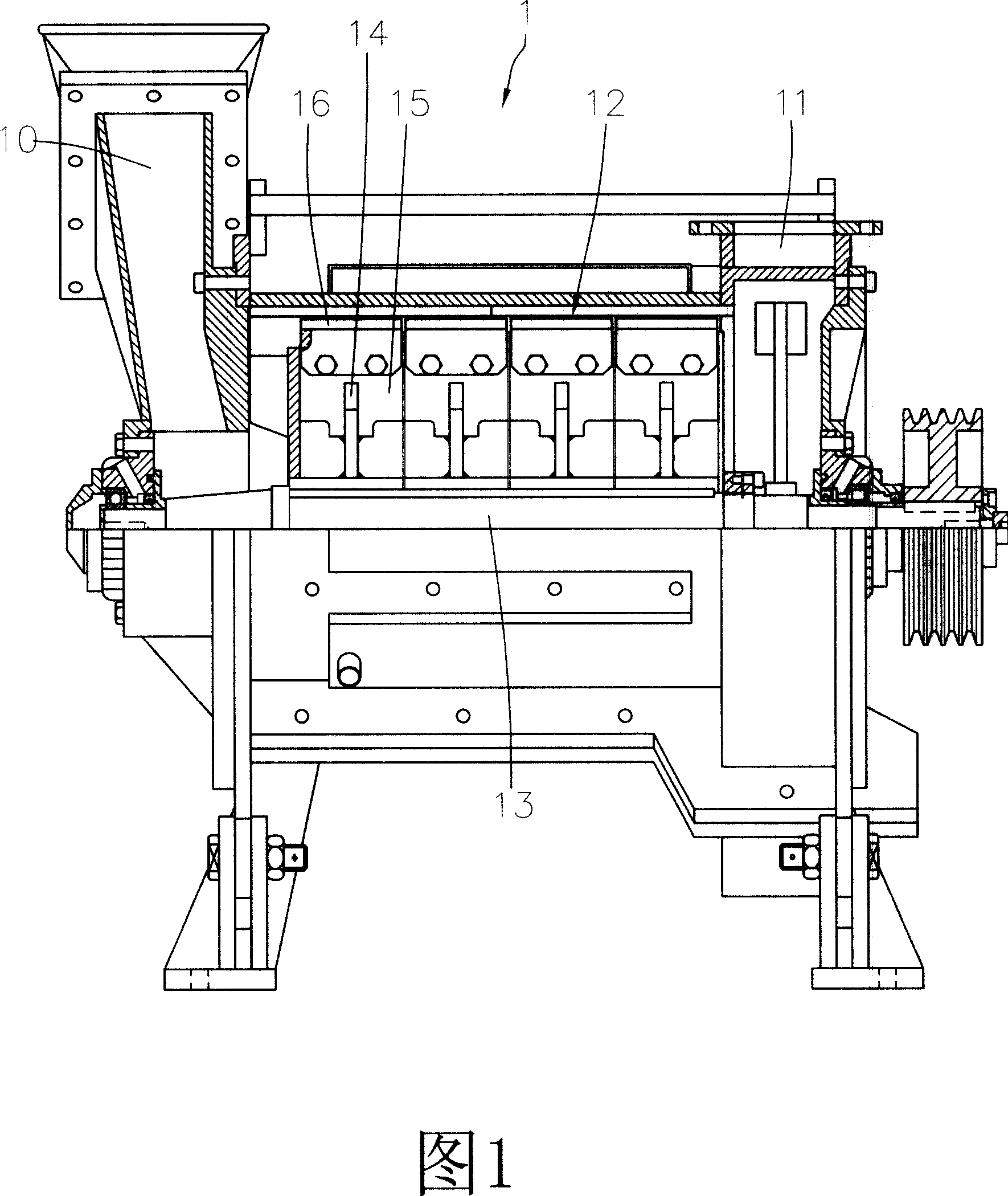
[0014] At first, please refer to Fig. 4, shown in Fig. 5, the present invention mainly is that one side of pulverizer 2 is provided with inlet 20, and opposite side is provided with outlet 21, pulverizer 2 is provided with pulverizing chamber 22, and pulverizing chamber 22 is provided with steps. shaped step groove 220, the crushing chamber 22 is provided with at least two or more crushing cutter heads 24, the powder cutting cutters 24 are assembled on the shaft 23 and driven by the shaft 23, and the crushing cutters 24 The tapering arrangement of outer diameters from large to small toward the outlet 21 corresponds to the step grooves 220 . The crushing cutter head 24 is provided with many distribution plates 25 and blades 26 .

[0015] D...


PUM


Abstract

A turbine crusher comprises an inlet at one side, an opposite outlet, crushing chamber inside with ladder slots and at least two crushing knife plates, which connect with shaft rod and driven by it, with the outside radius of the crushing knife plate tapered in arrangement to the outlet direction and corresponding to the ladder slots, material distributing plates and knives on the plate, with raw material sent into the crushing chamber for chopping, crushing along the crusher chamber toward the ladder slot, the crushed material falling into next step for secondary crushing to improve the crushing ratio.

Description

technical field [0001] The invention relates to a turbine pulverizer, which means that the pulverizer is provided with stepped grooves in the pulverization chamber, and the arrangement of the pulverization discs in the pulverization chamber, whose outer diameter gradually shrinks from large to small toward the exit direction, is consistent with each The stepped grooves form a correspondence; in this way, when the raw materials are poured into the crushing chamber for crushing, they are then squeezed along the crushing chamber to the stepped grooves through the principle of centrifugal force, and at the same time, the extruded raw materials pass through the bottom surface of the stepped grooves to form Block and then fall into the next stage and then carry out the second crushing. In this way, the crushed raw materials are squeezed and blocked through the stepped and tapered step grooves, and the crushing cutterhead with the tapered stages is used to give multiple crushing. The...

Claims


Application Information

Patent Timeline
Patent Type & Authority Applications(China)
IPC IPC(8): B02C18/06B02C18/18
Inventor 李庭帏
Owner 凌渊明
Why Eureka
Try Eureka