
Device for detecting three-axle parallel of large photoelectric monitoring equipment using thermal target technology

A technology for parallelism detection and measurement and control equipment, which is applied in the direction of optical devices, measuring devices, optical instrument testing, etc., can solve the problem that the frequency doubling technology cannot be used, the field measurement is not applicable, and the background technology cannot directly measure the parallelism between the laser and the infrared optical axis gender errors

Inactive Publication Date: 2007-07-18
CHANGCHUN INST OF OPTICS FINE MECHANICS & PHYSICS CHINESE ACAD OF SCI
View PDF0 Cites 28 Cited by
  • Summary
  • Abstract
  • Description
  • Claims
  • Application Information

AI Technical Summary

Problems solved by technology

[0006] The main problem of this device when it is practical is: because the pentaprism cannot pass through the infrared light, the background technology cannot directly measure the parallelism error between the laser and the infrared optical axis
Most of the laser rangefinders currently in use have a wavelength band of 1.06 μm, which is not in the visible band. When calibrating in the laboratory, the 1.06 μm laser can be converted into a 530nm laser by frequency doubling technology; but for the theodolite used in the field When it is necessary to calibrate the parallel shape of the optical axis, the frequency doubling technique cannot be used, and this method is not suitable for field measurement

Method used


Image

  • Device for detecting three-axle parallel of large photoelectric monitoring equipment using thermal target technology
  • Device for detecting three-axle parallel of large photoelectric monitoring equipment using thermal target technology

Examples


Embodiment Construction

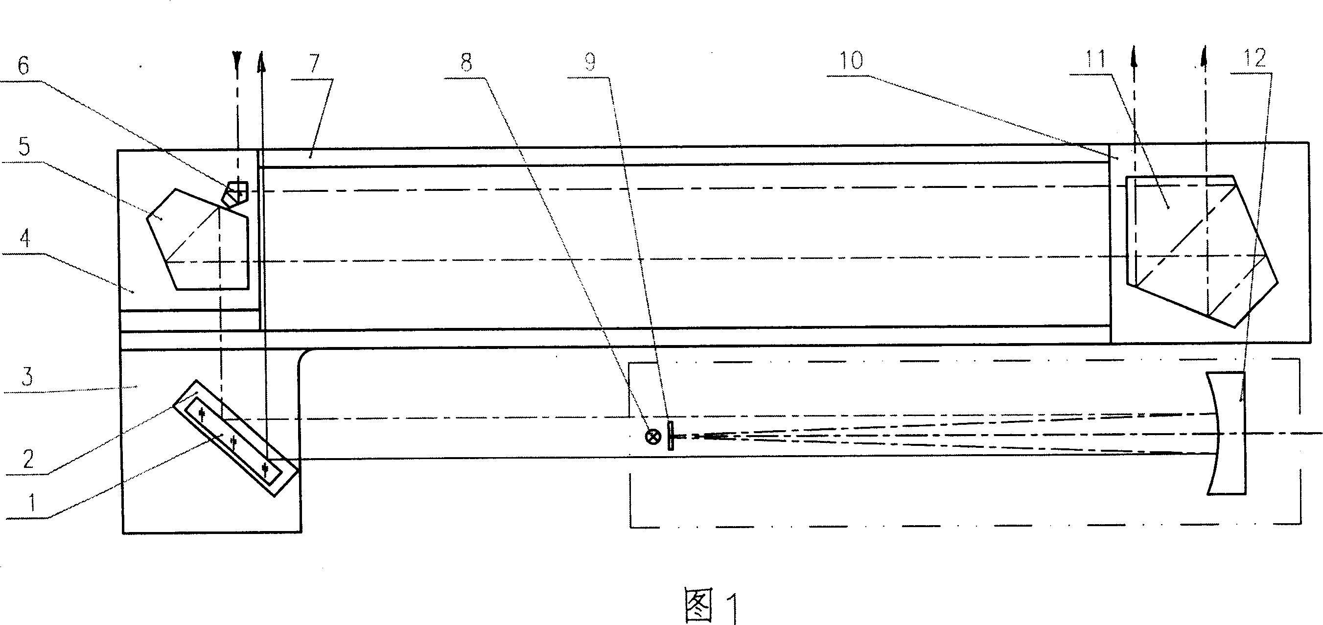
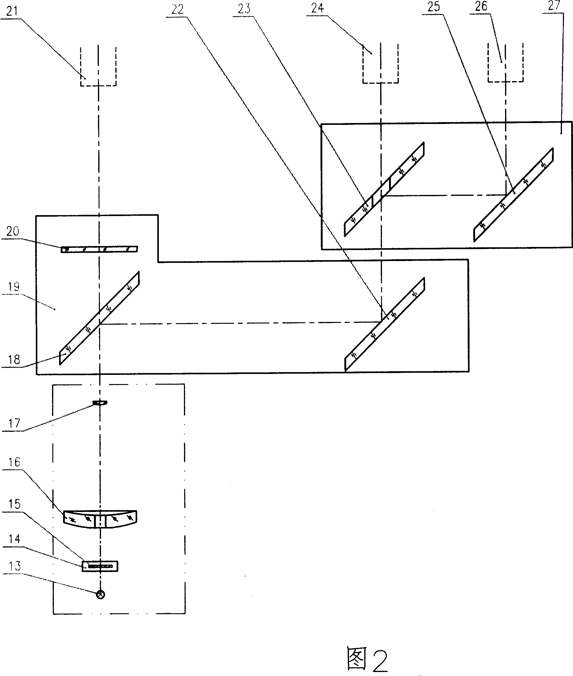
[0015] The present invention is implemented according to the structure shown in Fig. 2, wherein light source 13 adopts iodine tungsten lamp, has very wide spectral range, and thermal target slider 14 can move left and right, and the moving distance is greater than the line field of view of the collimated optical path system, and cannot Make the hot target out of the field of view of the collimated light path; there is a star hole in the center of the hot target. When the light source is turned on, the star hole is on the optical axis of the collimated light path. When the light source is turned off, the star hole on the hot target Moved outside the field of view of the collimated optical path, the area of ​​the hot target should be able to meet the requirements of the concentration of the laser energy emitted by the laser system laser of the tested instrument, and the absorption of laser energy to generate hot spots; the parabolic mirror 16 and the hyperbolic mirror 17 form a co...


PUM


Abstract

The invention relates to a device used heat target technique to detect tri-axiality parallel character for large scale photo-electricity test and control device. Its technology scheme is as follows: it includes light source, heat target and its slide rest, collimated light path, semi reflecting-photic lens, light reducing lens, three plane reflectors and lens seat; the heat target is set at the slide rest on the focal plane of the collimated light path of which optical axis orderly set light reducing lends, half reflecting-photic lens, the first reflector, the second plane reflector, plane reflector with center hole. All the reflectors except the light reducing lens are set on the collimated light path system optical axis with 45 degree and parallel. The invention can be used in three or more multi optical axis optical system parallel character testing.

Description

1. Technical field: [0001] The invention belongs to the technical field of optical instrument inspection and relates to a device for inspecting the three-axis parallelism of large-scale photoelectric detection equipment. 2. Background technology: [0002] Large-scale photoelectric measurement and control equipment generally refers to large-scale photoelectric tracking and measurement theodolites such as astronomical telescopes, tracking and measuring meteorological satellite systems, and resource survey remote sensing satellite systems. To meet the needs of its own functions, large-scale photoelectric equipment is equipped with TV tracking photogrammetry, infrared tracking measurement, and laser distance measurement. The three optical systems are aimed at the same target for measurement. In order to ensure the consistency of the measurement results, the optical axes of the three optical systems on the equipment must be parallel. If the optical axes of the three optical syst...

Claims


Application Information

Patent Timeline
Patent Type & Authority Applications(China)
IPC IPC(8): G01B11/27G01M11/00
Inventor 沈湘衡苏启顺叶露刘德尚张菠聂真威
Owner CHANGCHUN INST OF OPTICS FINE MECHANICS & PHYSICS CHINESE ACAD OF SCI
Learn More