Pollination device for orchid
A technology of pollinators and orchids, applied in the biological field, can solve the problems that can not be used for orchids, but only suitable for artificial pollination of melons and fruits, and achieve the effect of low cost, simple structure and high work efficiency
- Summary
- Abstract
- Description
- Claims
- Application Information
AI Technical Summary
Benefits of technology
Problems solved by technology
Method used
Image
Examples
Embodiment 1
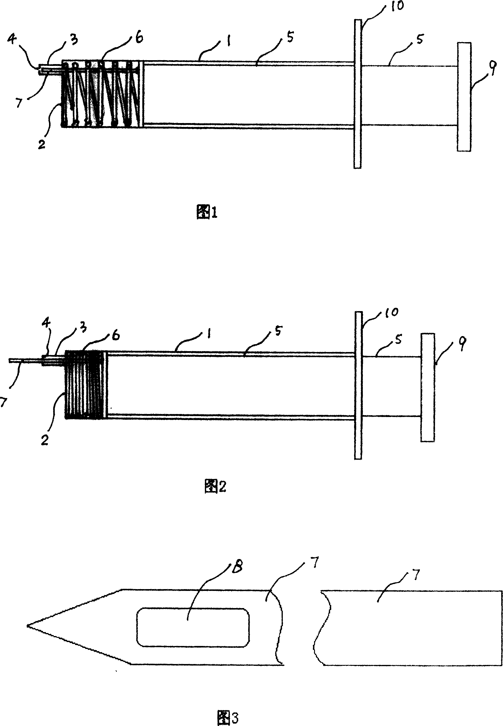
[0012] Embodiment 1: see Fig. 1~3. One end of the outer cylinder 1 is open and the other end has a bottom 2. The bottom 2 of the outer cylinder is provided with a small hole, and the small hole is connected with a thin cylinder 3 extending outward. The thin cylinder 3 also has a corresponding small hole 4, and one end of the push rod 5 Insert the open end of the outer cylinder 1 into the outer cylinder 1, and the push rod 5 is provided with a compression spring 6 between the end of the outer cylinder 1 and the bottom 2 of the outer cylinder. The small hole of the small hole and the small hole 4 of the thin tube 3 protrude and retract the pollination needle 7, and the pollination needle 7 is provided with a pit 8 that can accommodate pollen. 9 among the figure is the push handle of push rod 5, and 10 is the force piece that is located at the open end of outer cylinder 1. When in use, the operator puts the outer tube 1 between the index finger and the middle finger, and the upp...
Embodiment 2
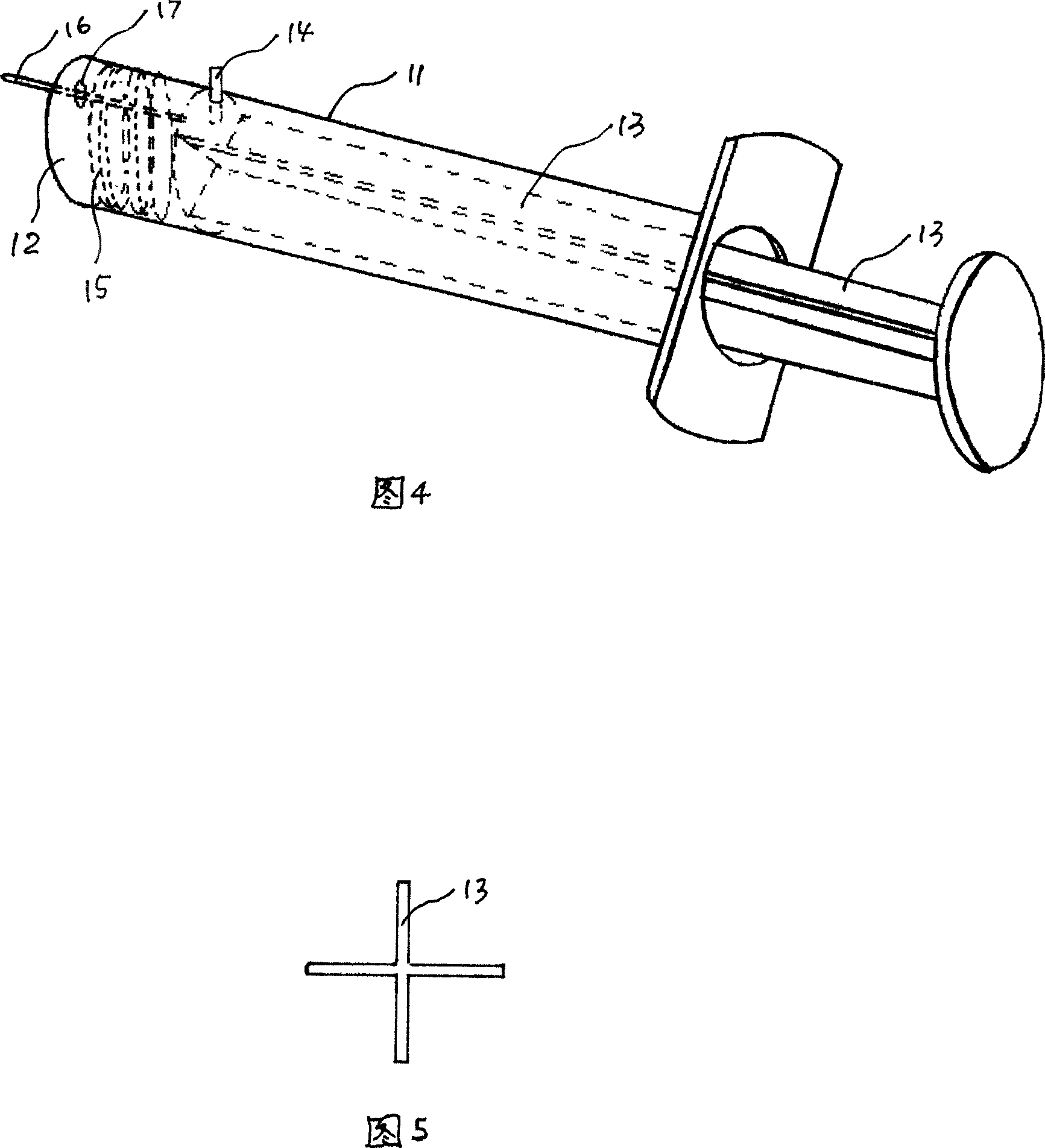
[0013] Embodiment 2: see Fig. 4 and. One end of the plastic outer cylinder 11 is open and the other end has a bottom 12 . The feature of this embodiment is that the section of its push rod 13 bar body is cross-shaped. 14 in the figure is the radial limit screw screwed in from the outer wall of the outer cylinder 11, which can prevent the push rod 13 from coming out. 15 is stage clip, and 16 is pollination pin, and 17 is aperture.
PUM
 Abstract
Description
Claims
Application Information
 - R&D
- Intellectual Property
- Life Sciences
- Materials
- Tech Scout
- Unparalleled Data Quality
- Higher Quality Content
- 60% Fewer Hallucinations
Browse by: Latest US Patents, China's latest patents, Technical Efficacy Thesaurus, Application Domain, Technology Topic, Popular Technical Reports.
© 2025 PatSnap. All rights reserved.Legal|Privacy policy|Modern Slavery Act Transparency Statement|Sitemap|About US| Contact US: help@patsnap.com


