Metal heald frame and heald shaft for a loom

A technology of healds and heald frames, which is applied in the field of heald frames and heald shafts for looms, and can solve the problems of complex and expensive embodiments

Inactive Publication Date: 2010-01-27
GROZ BECKERT KG
View PDF10 Cites 0 Cited by
  • Summary
  • Abstract
  • Description
  • Claims
  • Application Information

AI Technical Summary

Problems solved by technology

[0007] This embodiment is relatively complex and expensive

Method used


Image

  • Metal heald frame and heald shaft for a loom
  • Metal heald frame and heald shaft for a loom
  • Metal heald frame and heald shaft for a loom

Examples


Embodiment Construction

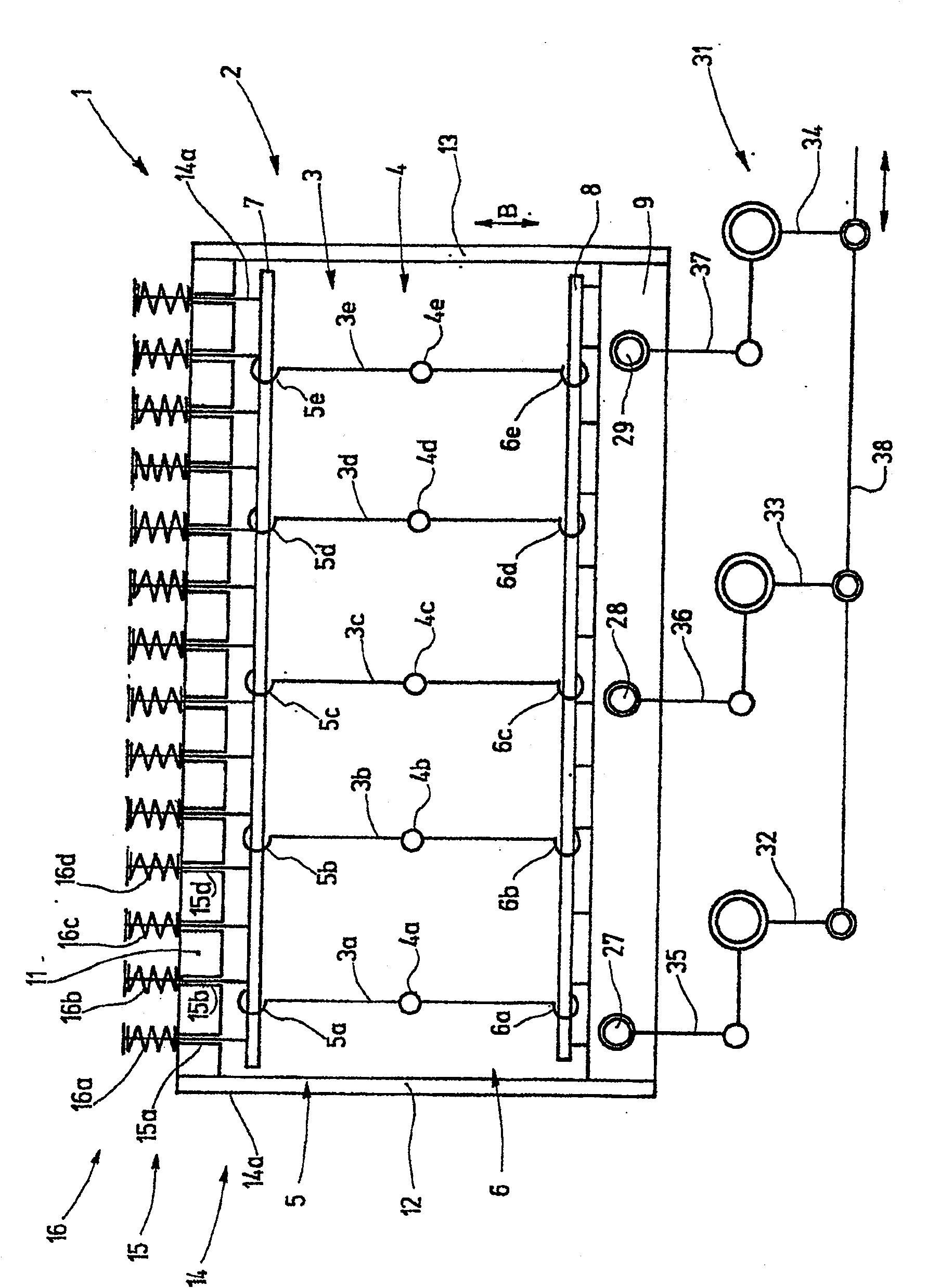
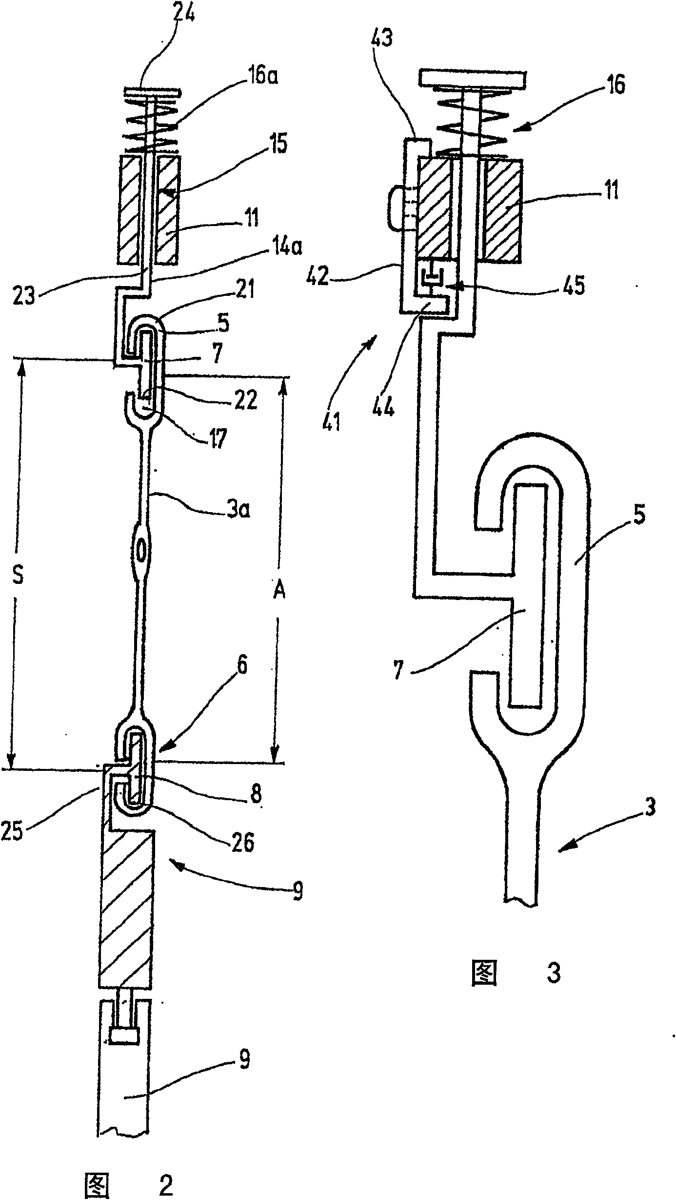
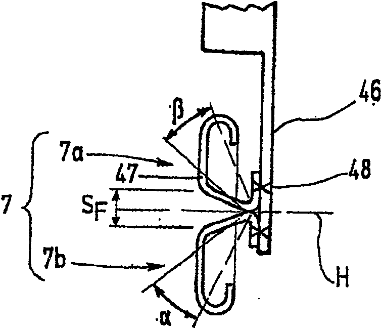
[0026] figure 1 The heald shaft 1 of the weaving machine, which is not shown further, is shown. The heald shaft 1 comprises a heald frame 2 carrying a plurality of healds 3 arranged parallel to one another. For display purposes, figure 1 Only five individual healds 3a, 3b, 3c, 3d, 3e are shown. In fact, more healds are spaced closer together. Each heald 3 has approximately in its center an eyelet 4 (4a, 4b, 4c, 4d, 4e) through which each warp thread passes through a corresponding heald eye. Each heald 3 is provided with a heald head 5, 6 (5a, 5b, 5c, 5d, 5e, 6a, 6b, 6c, 6d, 6e) on each end, by which the heddle 3 is held in the On the heald support rail 7,8. The heald support rails 7 , 8 are supported by the heald frame 2 and extend at a distance from one another and parallel to the direction of movement B of the heald frame 2 , which corresponds to the longitudinal direction of the heald 3 . The heald support rail 8 is held rigidly on the heald frame 2 , which comprises ...


PUM


Abstract

The present invention provides a heald shaft (1), comprising healds (3) which are mounted with zero or little backlash, is provided with at least one heald carrying rod (7) which is moveably mounted for elastically tightening the healds (3) as a whole or which is provided with at least one moveably mounted part (55). A spring means (16,56) is used to apply a tightening force to the head (5) of each heald (3) for zero-backlash mounting thereof. This enables a loom provided with one such heald shaft to operate at a high speed without the healds becoming woven into the heald carrying rods or excessive noise being produced.

Description

technical field [0001] The invention relates to a heald frame, in particular for a weaving machine. Background technique [0002] The shaft Schaft of a weaving machine, also called a heald shaft Webschaft, is formed by a heald frame on which a plurality of healds are held. Each heald (Litz) has a heald eye for the passage of warp threads. Movement of the axis in the longitudinal direction of the heald thus moves the warp threads out of the plane of the warp threads, forming a shed, for example for the insertion of weft threads. [0003] In modern looms, the heald shaft reciprocates at high speed. Acceleration and braking forces are so great that the heald stops, which are generally held on the heald frames with some play, rest on their supports and engage in them. This process causes noise and wear and limits the operating speed of the loom. [0004] Attempts have therefore been made to reduce the play of the heddles on the heald frame. German utility model G 94 13705 t...

Claims


Application Information

Patent Timeline
Patent Type & Authority Patents(China)
IPC IPC(8): D03C9/06
CPCD03C9/0691D03C9/0633
Inventor J·布鲁斯克G·比希勒
Owner GROZ BECKERT KG
Why Eureka
Try Eureka